Thx for all info
Hi All
Just stumbled on this post and wanted to say thx to all the advices in there.
I am a beginner as well and just starting on a 3240 (same but "amp only, not receiver") which blows its fuses (F501 502) at startup.
So far I have pinpointed 423 and 431 as being shorted, but even with them (and 435) renoved, it is still blowing
Following docs from here and hifiEngine for both the 3240 and the 7240, I realised that there are apparently 2 "makes" of them by NAD, one (the oldest?) using SB826 SB649A, the other (more recent?) using BD912 BD680.
Otehrwise, if anybody ends up like HVfanatic here for the bias adjustment procedure, the docs in hifiengine give the whoel process in details, and the recommended value is 30mV...
ONE question is anybody here is willing to help:
what are the P.T.C.1 and P.T.C.2 in the schematic (on the rails). I can;t find them in the nomencalture, not identify htem on the board. Are they these "wire links" to the main switch? Why have they a resistor symbol with a A value?
I'll keep you guys posted.
Without seeing the circuit my guess would be either thermistors PTC = positive temperature coefficient which is standard labelling.
Wire links across low value resistors are seen in some amps, the idea is you snip the link to measure the volt drop across the low value resistor and hence calculate the current.
Post a screen snip of the circuit
Edit I can see them in the diagram in post #1. They are drawn as thermistors but I suspect they are either "polyswitches" (which are like a bit a thermistor) which have a low resistance until a set current is exceeded and then they "flip" to a high resistance. Used as resettable fuse. Or they could be thermal fuses that go open circuit at a specific temperature. These are non resettable.
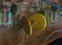
If you post a close up detailed photo of the part we could probably ID it for sure.
Wire links across low value resistors are seen in some amps, the idea is you snip the link to measure the volt drop across the low value resistor and hence calculate the current.
Post a screen snip of the circuit
Edit I can see them in the diagram in post #1. They are drawn as thermistors but I suspect they are either "polyswitches" (which are like a bit a thermistor) which have a low resistance until a set current is exceeded and then they "flip" to a high resistance. Used as resettable fuse. Or they could be thermal fuses that go open circuit at a specific temperature. These are non resettable.
If you post a close up detailed photo of the part we could probably ID it for sure.
Thanks a lot Mooly
I think you are right they are thermistors used as cut-of limiters (see pic attched). At cold they measure as a short
So far here is where I am:
I have tested OK the 4 mains caps (505/50 509/510) (DMM C function)
I have tested Ok the 2 diodes bridges (DMM D function)
I have --at my big surprise-- tested OK (DMM D function) the 4 outputs transistors 427 428 429 430
I have indentified 3 shorted transistors:
423 431 434
Their counterparts 425 433 424 432 426 were tested OK...I may change them eventually to match whetever I put on for the
faulty ones...
I have also tested OK 419 417 421 420 418 422
I have also tested OK 401 405 403 407 (and 409 /411 / 413/ 415)
And also 435 437 436 438
Note that 434 433 were BD911, no SD 1026..and 432/432 were bd912, not sb826....a/ they looked like "factory made" hence
maybe another revision from NAD and b/ specs are Ok i believe.
I have removed the three shorted ones, but the thing keeps blowing its 4 fuses (Amp section only, the preamp is fine)
as soon as plugged in.
Note that I ran short of 4 and 5 amps fuses, so I used 1A ones for this test...But the capa charging at startup would
no draw more than that woudl it?
Note also that I haven't setup a bulb dimmer yet eitehr :/
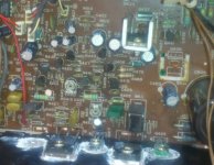
Note that the PCB looks "roasted" in the areas around of q411 and q415 which I surprisingly tested OK (taken out, not
in circuit)XXXXXXXXXXXXXXXXXXXXXXXXXXXXXXXXXXXXXXXXXXXXXXXXXXXXXXXXXXXXXXXXXXXXXXXXXXXXXXXXXX
Are diodes worth checking?
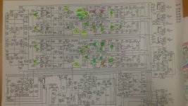
I also attach the schematics from HFE which is easier to read IMHO than this one.
I am thinking of removing the ptc1 and ptc2 for the next test...looking like it may help me identify the fauly aread of
the circuit?
Any advice as to "where to look next" would be much welcome! I must admit I'm kind of lost now...don't want to be
poking out every single componet at random, and until these fuses hold on I can't even measure a voltage anywhere...
THX in advacne
https://drive.google.com/folderview?id=0ByEVCkdPuxbTbEZjTC1hY0hWM0k&usp=sharing
I think you are right they are thermistors used as cut-of limiters (see pic attched). At cold they measure as a short
So far here is where I am:
I have tested OK the 4 mains caps (505/50 509/510) (DMM C function)
I have tested Ok the 2 diodes bridges (DMM D function)
I have --at my big surprise-- tested OK (DMM D function) the 4 outputs transistors 427 428 429 430
I have indentified 3 shorted transistors:
423 431 434
Their counterparts 425 433 424 432 426 were tested OK...I may change them eventually to match whetever I put on for the
faulty ones...
I have also tested OK 419 417 421 420 418 422
I have also tested OK 401 405 403 407 (and 409 /411 / 413/ 415)
And also 435 437 436 438
Note that 434 433 were BD911, no SD 1026..and 432/432 were bd912, not sb826....a/ they looked like "factory made" hence
maybe another revision from NAD and b/ specs are Ok i believe.
I have removed the three shorted ones, but the thing keeps blowing its 4 fuses (Amp section only, the preamp is fine)
as soon as plugged in.
Note that I ran short of 4 and 5 amps fuses, so I used 1A ones for this test...But the capa charging at startup would
no draw more than that woudl it?
Note also that I haven't setup a bulb dimmer yet eitehr :/
Note that the PCB looks "roasted" in the areas around of q411 and q415 which I surprisingly tested OK (taken out, not
in circuit)XXXXXXXXXXXXXXXXXXXXXXXXXXXXXXXXXXXXXXXXXXXXXXXXXXXXXXXXXXXXXXXXXXXXXXXXXXXXXXXXXX
Are diodes worth checking?
I also attach the schematics from HFE which is easier to read IMHO than this one.
I am thinking of removing the ptc1 and ptc2 for the next test...looking like it may help me identify the fauly aread of
the circuit?
Any advice as to "where to look next" would be much welcome! I must admit I'm kind of lost now...don't want to be
poking out every single componet at random, and until these fuses hold on I can't even measure a voltage anywhere...
THX in advacne
An externally hosted image should be here but it was not working when we last tested it.
https://drive.google.com/folderview?id=0ByEVCkdPuxbTbEZjTC1hY0hWM0k&usp=sharing
Whoa... slow down We've gone from trying to id a part to this
First thing... your pictures don't show so try attach them directly to the forum.
To add a photo, files or non standard files.
First click "go advanced" in the box below the "quick reply" message box. Doesn't matter if you decide half way through a message to do that, it carries it forward.
Then click "Manage attachements". Maximise the new Window so that you can see all the text.
Click browse in the first box at the top and find your picture. Repeat for any more pictures.
Click upload... a message appears "uploading"
When complete the files will show as being attached. Now click the small text that says "close this window"
The pictures should now be attached and when you submit your post they will appear.
Make sure your pics aren't too big, a couple of 100k is plenty, and many members object when they are massive and it alters the margins
It tells you in the attachments window what max sizes are allowed.
If you want to attach a file that has a non standard format for example excel, circuit simulation etc then try putting the files in a zipped folder and attaching that.
For faultfinding you have to follow a definite plan and the first step must be a bulb tester. When you have that rigged up then we can work on one channel at a time and diagnose and repair it. The amp has to be put into various "safe" conditions that allow readings to be taken to determine what is going on.
We've gone from trying to id a part to this First thing... your pictures don't show so try attach them directly to the forum.
To add a photo, files or non standard files.
First click "go advanced" in the box below the "quick reply" message box. Doesn't matter if you decide half way through a message to do that, it carries it forward.
Then click "Manage attachements". Maximise the new Window so that you can see all the text.
Click browse in the first box at the top and find your picture. Repeat for any more pictures.
Click upload... a message appears "uploading"
When complete the files will show as being attached. Now click the small text that says "close this window"
The pictures should now be attached and when you submit your post they will appear.
Make sure your pics aren't too big, a couple of 100k is plenty, and many members object when they are massive and it alters the margins
It tells you in the attachments window what max sizes are allowed.
If you want to attach a file that has a non standard format for example excel, circuit simulation etc then try putting the files in a zipped folder and attaching that.
For faultfinding you have to follow a definite plan and the first step must be a bulb tester. When you have that rigged up then we can work on one channel at a time and diagnose and repair it. The amp has to be put into various "safe" conditions that allow readings to be taken to determine what is going on.
Before plugging it in again, I have a couple of specific question. I have been trying very hard to understand the schematic...
When on 4ohm impedance switch, the +/-71V rails are not powered up. How is the whole "front-end" of the amp section supposed to be powered, i.e. upstream from D417/418/419/420 ?
-edit- I'm stupid, that's the low volateg rail which is not powered when on 4ohms, not the high one :-/ -/edit-
THX
When on 4ohm impedance switch, the +/-71V rails are not powered up. How is the whole "front-end" of the amp section supposed to be powered, i.e. upstream from D417/418/419/420 ?
-edit- I'm stupid, that's the low volateg rail which is not powered when on 4ohms, not the high one :-/ -/edit-
THX
Last edited:
OK, it should make more sense as we test and check the amp. Tbh I would be looking at replacing several of the semiconductors but its good to go through it all and confirm the faults.
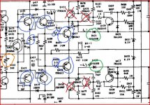
So first steps are to remove the high voltage switching transistors and their drivers on both channels. These are marked in red. These only come into play at high volume so the amp will work correctly without them and it can be tested in this condition. Out of circuit and they can be more fully tested but I would be looking to replace them with matched sets of newer devices.
The two diodes circled in green should be tested. These are "commutation" or switching diodes and are vitally important. They isolate the high and low rails from each other and allow the low voltage rail to power the output stage when the rail swithing transistors Q431 and 433 are off. If you wanted to replace them then something like the BY399 should be suitable.
The preset pot marked in orange should be turned to maximum resistance (giving 1560 ohms approx between B and E. This gives the lowest quiescent current in the output stage. Do that for both channels.
The six transistors circled blue (drivers, pre drivers and outputs) should be checked and replaced as necessary. Also check the two 3.3 ohms and 1K also marked.
That should give you a working amp minus the high voltage rail switching. When the amp is confirmed working and OK is when the rail switching transistors can be replaced and the rail switching tested and confirmed as OK.
If you want to work on one channel using parts you have (maybe using parts from both channels to make one good one initially) then removing the outputs and drivers from one channel should allow the other channel to be rebuilt and tested safely. With the amp in this state it should power up OK with the bulb tester.
Attachments
Whaoo thx a lot mooly that sounds promising.
In the meantime before your message, I had done some measurements as , in 4 Ohms position, the fuses hold on when in series with 15W of bulb (with the 71V of the rail becoming a 11V instead).
I noticed then a huge DC offset on the ouputs (-1V)..which didn't get adjusted when playing up with VR403 / 404. I realised then that the manual specified this offset HAD to be adjusted in the 8omhs position/...so I tried again powering up the lower rail. I noticed then a sizzling noise coming from one of the 6800uF on the lower rail...and maybe saw it starting to bulge. Even though I "measured" the 4 big caps ok out of circuit (capacitance meter from my DMM), it looks like at least one of them may not be holding up voltage, even a very low voltage like that...
I'll replace these big caps, but in the mean time (Can't have them before monday), just to know, would it be SAFE to power-up the amp (with bulb dimmer) without the caps for voltage measurements? The DC would be very dirty with 50hz, but would it be so dirty as to prevent doing just some DC measurements?
THX again
Definitely don't power it up with any of those four caps omitted, in fact if those caps are failing then I would replace all four. With any missing, any readings would be meaningless and it could well cause more problems, but that said, even a 1000uf and above would allow you to at least work on the amp.
I'm now on to my second 7240PE repair.
In my case, I've had real trouble getting this one working. The right channel blows both the R465 and R467 rail 68ohm resistors and the 5A fuse.
I checked and replaced if required the Q427,Q429, Q425, Q417, Q423, Q431, Q435, Q433, Q437 - so they are all now ok. On power on (I am in a temorary house and cannot find my light bulb tester) on normal/4ohm setting and with soft clipping circuit bypassed (off) I get smoke from R465/467 then a flash and they're gone, usually with the RH 5A fuse - this leaves the output transistors Q427 and Q429 hot to touch.
I've checked the rest of the circuit with no apparent faults anywhere. From memory when I was testing with main driver transistors removed, the RH channel ones had twice the rail volatage on one leg as compared with the good channel. I started tracing this back through the circuit but got lost.
If anyone has any ideas from this info, or some guidance as to where to look next, I would be very appreciative.
Regards - AJ
That was it - Q419/421 replaced and system was ok. Like an earlier poster - and I've done this twice now - while doing final checks and adjustments - one slip of the probe and I had lots if magic smoke from the good channel - so had to rebuild both channels. All done now - adjusted and playing nicely. Thanks again to the great info from members in this forum.
- Status
- This old topic is closed. If you want to reopen this topic, contact a moderator using the "Report Post" button.
- Home
- Amplifiers
- Solid State
- Nad 7240pe damaged amp section