hello fellows
and NAD 3020 lovers
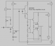
I made this very simpified schematic ( see attachement )
to show the basic function of
Bjoern E creation from 1979 ( soon 30 year old idea, still working good! )
NAD 3020i
It should be noted, that just because they discovered 2+2 = 4 some thousands of years ago,
this does not make this idea less valid in the year 2008.
Same in chess, which I play daily on internet.
A good move played in the 17th century, is not a bad move now.
Because this is the nature of mathematical, logical things.
And all amplifiers obeys by laws of mathematical expressable formulas.
Be it Ohms Law or other elektronical laws ....
This isalso why our Spice Sims works at 99.5%.
They use formulas for electrical physical things & by such nature.
My simplified schematic.
This can make us, hopefully, understand how the NAD 3020 overall idea is.
And it is is a very good audio amp idea, I would say.
regars, lineup
and NAD 3020 lovers
I made this very simpified schematic ( see attachement )
to show the basic function of
Bjoern E creation from 1979 ( soon 30 year old idea, still working good! )
NAD 3020i
It should be noted, that just because they discovered 2+2 = 4 some thousands of years ago,
this does not make this idea less valid in the year 2008.
Same in chess, which I play daily on internet.
A good move played in the 17th century, is not a bad move now.
Because this is the nature of mathematical, logical things.
And all amplifiers obeys by laws of mathematical expressable formulas.
Be it Ohms Law or other elektronical laws ....
This isalso why our Spice Sims works at 99.5%.
They use formulas for electrical physical things & by such nature.
My simplified schematic.
This can make us, hopefully, understand how the NAD 3020 overall idea is.
And it is is a very good audio amp idea, I would say.
regars, lineup
Attachments
Problems
Hi i have put in the 4R7 resistors.
Now i want to adjust the bias but i cant find the solder shorts.
In the service manual is written:
1: Remove input signal and load, set impedance switch to 8oms (Reset to 4 ohms when finished).
2:Remove solder short across R455 and R456
3:Connect DMM across P403 (-) and P404 (+)
4:Turn on and adjust R443 for reading of 28mV (+-2mV)DC
5: Repeat, using P405 (+) and P406 (-), adjust R444
Leave Power on for minimum 5 minutes with no signal connected.
Repeat adjustments.
When finished replace soldershorts across R455 and R456.
But i dont know where the solder shorts between R455 and R456 is.
I have a Nad 3020i, anybody have a picture of this solder short?
Thanks
Re: Problems
Hi
Near the heatsink, there are two small 1 Ohm resistor, is this resistor that is shorted.
Inspect with a multimeter and you will see that instead of 1 Ohm it will measure 0 Ohms.
All you have to do is to remove the solder short of this resistor, adjust bias and short again...
jjanderson said:
Now i want to adjust the bias but i cant find the solder shorts.
Hi
Near the heatsink, there are two small 1 Ohm resistor, is this resistor that is shorted.
Inspect with a multimeter and you will see that instead of 1 Ohm it will measure 0 Ohms.
All you have to do is to remove the solder short of this resistor, adjust bias and short again...
jjanderson said:yes i found the 1ohm resistors but i cant find any solder short there?!?
is the resistor directly shorted? or is the short somwhere else?
Thanks
The resistor is shorted by a solder bridge in the opposite side of the PCB.
jjanderson said:
Is ist possible the the resistors are faulty?
Everything is possible.
Remove the resistor from circuit and measure again...
jjanderson said:yes i have done that but the result is the same no gateway through the resistors.
It seems that somone removed the solder shorts and that the resistors are faulty.
thanks
Its possible.
Put in another 1 Ohm resistor, and inspect again...
i would pull all transistors in that area and check them for shorts ( search google on how to do this, check things systematicly just because you find one faulty component doesnt mean there are no more, you may want to look into a variac or something similar so you dont keep blowing things when you switch on to test it as well.
thanks
chris
thanks
chris
- Status
- This old topic is closed. If you want to reopen this topic, contact a moderator using the "Report Post" button.
- Home
- Amplifiers
- Solid State
- NAD 3020 drivers