Burnedfingers,
Is the top list of voltages when it is working or not working, same for the bottom list, working or not working. Also pin 3 and 8 are tied together so they should read the same no matter what. Check and make sure you counted the pins correctly. Also what are the voltages on the upper tube of the cascode, there should be clue there too.
Craig
Burnedfingers,
I just figured out your voltage lists, I was looking at it wrong. Andy used a tube for each side of the cascode, I was thinking a tube for the upper and a tube for the lower, clear as mud now. Anyway the side with 363VDC is way too high for a 6DJ8, so I would have say that tube is NOT conducting, is the heater lit up? The professional soldering OK on the tube socket? Swap tubes around and see if the voltages follow.
Craig
Thanks for the response Craig ")
Heater connections are ok. Swapped tubes and voltages stayed within a few volts of what I posted. I pulled one of the LM334-z's and nothing changed so I re-installed it and took out the other LM334-Z and blew the zener diode so I am assuming that one of the LM334-Z's wasn't working. But then I could wrong
Heater connections are ok. Swapped tubes and voltages stayed within a few volts of what I posted. I pulled one of the LM334-z's and nothing changed so I re-installed it and took out the other LM334-Z and blew the zener diode so I am assuming that one of the LM334-Z's wasn't working. But then I could wrong
Is there a voltage on the schematic for pin8 ? Your photo is cut off where the line is leading to it. With the cross-coupling you are getting voltages that normally wouldn't be there if the tube was not conducting, hard to tell from here. For example, there would be no voltage on pin 6 if the that tube was not conducting, so the voltage is coming from the cross-coupling. You know it's going to be something real stupid, it always is. Keep at it. Oh, can you tighten the pins in the socket, that's always a forgotten problem.
Craig
Craig
The voltage on pin 8 on the input side was 2.46 and 2.41 on the other side.
Plate voltage is roughly 100 low on the input side and 100 high on the other side. Your right its probably something really stupid but I'll be darned if I see it right now. I'm about frustrated enough
to pull it out and throw it in the garbage and put in something that works.
Plate voltage is roughly 100 low on the input side and 100 high on the other side. Your right its probably something really stupid but I'll be darned if I see it right now. I'm about frustrated enough
to pull it out and throw it in the garbage and put in something that works.
Ok, plate voltages are more in the ball park now. Recent tests now show that the current sources are to blame for its inability to produce a nice clean sine wave. The signal is good on the input side of the tube and gets nasty looking on the feedback side.
So the question now is can I replace these CCS's with a different CCS board.
So the question now is can I replace these CCS's with a different CCS board.
Yes. I didn't get a chance to draw up a schematic today, so I'll wave my hands:
If you use the cascode bipolar circuit, use a couple of reasonably fast NPNs, like 2N5210 or '2222 or the like. Connect the bottom of the CCS to the negative rail, then use something like a 200k resistor to feed the LED references from the B+. The zeners can be clipped out, along with the resistors that set the original CCS chips' currents.
I don't see any logic in using two parallel CCS.
SY,
If you could post it I would appreciate it as I cannot find my CCS board and schematic information. I have 100 or so 2N5210 transistors on hand so they aren't a problem.
llwhtt,
Thanks for the reply. I believe the material I have states 5.8mA (170-175) voltage drop so the 6.5mA would be right in the ball park. If I had some LM334-Z's on hand I would try another pair per side but I do have some nice little CCS boards courtesy of SY that I could try.
There are so many voltages listed for the same node it 's hard to tell what number goes with what number. I got to thinking maybe one is for ST70/MKIV and the other set for the MKIII, don't know. Anyway at 5.8ma times 2 we're still over the limit of a single 334. Looks like you're on the right track though.
Craig
Craig
Print board layout:
http://www.diyaudio.com/forums/atta...tamp=1138453582
Schematic:
http://www.diyaudio.com/forums/atta...tamp=1138481795
Those are from thread : CCS for tubes/valvesCB's
links don't work now must be too old.
Someone had detailed directions on the boards and I think it was Planet10 if memory is correct.
http://www.diyaudio.com/forums/atta...tamp=1138453582
Schematic:
http://www.diyaudio.com/forums/atta...tamp=1138481795
Those are from thread : CCS for tubes/valves
CB'slinks don't work now must be too old.
Someone had detailed directions on the boards and I think it was Planet10 if memory is correct.
Here's the original thread:
http://www.diyaudio.com/forums/showthread.php?s=&threadid=72740&highlight=CCS
Here's the documentation:
http://homepage.mac.com/tlinespeakers/FAL/downloads/diyAudio-CCS-beta3.pdf
http://www.diyaudio.com/forums/showthread.php?s=&threadid=72740&highlight=CCS
Here's the documentation:
http://homepage.mac.com/tlinespeakers/FAL/downloads/diyAudio-CCS-beta3.pdf
For a triode stage, yes. For UL or pentode, no. The resistors help stabilize the output stage against oscillation; the bigger they are, the more effective. The limit is the pole caused by the RC time constant with the tubes' input capacitance. UL and pentode tend to have pretty low input capacitances because of the partial amelioration of the Miller effect. Triodes are not so lucky...
FWIW, my pentode amps use a much higher value than that (33-47k), both as grid stoppers and to minimize the loading of the driver when the output tubes clip.
FWIW, my pentode amps use a much higher value than that (33-47k), both as grid stoppers and to minimize the loading of the driver when the output tubes clip.
Tube God dyna board
b-siko@hotmail.com
Ihave an exact perfectly clear schematic that I made in a bmp file if you would like e me and i will send it to you.
b-siko@hotmail.com
Ihave an exact perfectly clear schematic that I made in a bmp file if you would like e me and i will send it to you.
I just picked up an old ST70 in need of some work that uses this same board.... it also has an interesting external solid state power supply.... if you still have schematics and wiring info or can point me to an appropriate link, I would sure appreciate it.
Thanks in advance!
Bill
Thanks in advance!
Bill
success - obtained information and schematic on tube god mod for st70
I was fortunate to have been able to reach Andy Fuchs and he was kind enough to share a schematic for the board as well as some basic operational information.
I really appreciate having access to the amazing breadth of knowledge this forum provides. Thanks!
Bill
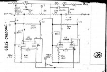
The associated information he provided is as follows:
Here is the schematic for the board. The 100-k input is the audio (from jack). The 20-k input is the feedback (via a resistor from the 16 ohm tap. The B+ should be 400-V and the tubes should be 200 on top plate and 100 on bottom plate. They should be selected to be around those equal splits in voltage. The tail input via the 5-K ½-W comes from the bias supply. A single point ground is suggested. Filaments should be elevated by 50 volts. That can be made from the b+ with a couple of resistors and a cap, or my making a bias type supply but for 50 V positive. Have fun.
I was fortunate to have been able to reach Andy Fuchs and he was kind enough to share a schematic for the board as well as some basic operational information.
I really appreciate having access to the amazing breadth of knowledge this forum provides. Thanks!
Bill
The associated information he provided is as follows:
Here is the schematic for the board. The 100-k input is the audio (from jack). The 20-k input is the feedback (via a resistor from the 16 ohm tap. The B+ should be 400-V and the tubes should be 200 on top plate and 100 on bottom plate. They should be selected to be around those equal splits in voltage. The tail input via the 5-K ½-W comes from the bias supply. A single point ground is suggested. Filaments should be elevated by 50 volts. That can be made from the b+ with a couple of resistors and a cap, or my making a bias type supply but for 50 V positive. Have fun.
Attachments
- Status
- This old topic is closed. If you want to reopen this topic, contact a moderator using the "Report Post" button.
- Home
- Amplifiers
- Tubes / Valves
- Mystery ST-70 Driver Board