Layout is the way to deal with RF problems, closely followed by decoupling and resistive damping. Push-pull circuits invite positive feedback because there is always an input with the right phase. That is why RF valves intended for push-pull duty usually have a pin layout which reduces this risk - the ECC88 does not because it was intended for cascode duty.
I've done quite a lot of RF layout work in the past, and I thought carefully when I was laying out this circuit. That doesn't mean that I haven't done something stupid, though! The entire circuit is laid out over a ground plane with very short trace lengths and power supply decoupling. Maybe adding some high-frequency decoupling across the tail CCS will be beneficial.
Interestingly enough, I have only used E88CCs in cascode configuration in the past. (I've just noticed that my browser autocorrects "cascode" to "cascade", which is annoying!), which may be why I have never had any RF instability issues with them before.
Interestingly enough, I have only used E88CCs in cascode configuration in the past. (I've just noticed that my browser autocorrects "cascode" to "cascade", which is annoying!), which may be why I have never had any RF instability issues with them before.
Could the oscillation be in the SS part of the circuit? Try touching the tail CCS at various nodes with your finger - a useful RF damper and safe where only low power is possible. Some injected hum may occur, but any change in random noise or DC conditions suggests RF instability.
Having spent some time with the circuit on the bench, it looks like RF oscillation is the problem after all. But rather annoyingly, nothing I have tried seems to kill it. Even ferrite beads on the anode connections made no difference.
I'm thinking that the E88CC was not a great choice of valve for this stage (I just rather like them and happened to have some in stock) and am going to try some experiments with ECC81s instead. Unfortunately I am stuck with a 200V HT voltage (unless I replace the mains transformer), so I think I'll need to operate with a fairly low tail current - probably around the same 11.5mA that I used for the E88CCs - and set the quiescent anode voltage to about 130V in order to achieve half-decent linearity.
I'm thinking that the E88CC was not a great choice of valve for this stage (I just rather like them and happened to have some in stock) and am going to try some experiments with ECC81s instead. Unfortunately I am stuck with a 200V HT voltage (unless I replace the mains transformer), so I think I'll need to operate with a fairly low tail current - probably around the same 11.5mA that I used for the E88CCs - and set the quiescent anode voltage to about 130V in order to achieve half-decent linearity.
Have you tried adding a cathode stopper? A few hundred ohms right at the cathode connections. A ferrite bead might work instead.
My thinking goes as follows:
1. the valve doesn't know it is supposed to be a LTP
2. all it sees at its cathode is some stray capacitance with very little damping resistance
3. followers with capacitive loading often oscillate
If you could narrow down the frequency of oscillation this might help find a cure.
If you're experiencing RF oscillations with the ECC88 and variants, make sure any decoupling is bang-on the tube sockets and as short as possible, exactly as per the older TV turret tuners. For preamps using video/RF/ flighty gm tubes I always use the top chassis around the tubes as ground, as opposed to a thick copper bus earthed at one point which is inductive. This tube WILL oscillate freely at 450Mc/s when given the chance, often without the user noticing it and acting as a noisy mixer/ demodulator with audio signals. Screening cans also help.
Generally a self oscillation will show a shift in the DC working point shift, a finger close to tube will often a discrepancy.
richy
Generally a self oscillation will show a shift in the DC working point shift, a finger close to tube will often a discrepancy.
richy
Last edited:
I've got a GDM from my G8 days but it isn't very sensitive...til 215 MHz.
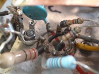
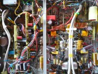
Post 21 Elvee; In many cases I found a CCS as an anode load substitute will make a highish gm tube oscillate as there is little damping, as tube parasitics come into dominance. Also the layout becomes dicy when compared to using a resistor.....clip of my preamp output stage # physical layout around both ECC88 sections paralled as a cathode follower... follows fairly tight practice...of wiring components directly to holders. Note the light blue ceramic cap directly on tube pins and the closest possible grounding, supplemented by a higher value on the ajacent side. Spot the ferrite beads added as a precaution, despite no RF oscillatory mode present, I still added them....and grid resistors 5K6 (as dampers) wired direct to grids.
This preamp is quiet enough for studios; noise -100dB down A weighting, capable of output levels +25dBu into 600 ohms and yes it uses transformers for both in/out. -3dB @ 60KHz...THD is very low too.
A real performance advantage is to dump the traditional method of mounting the tone control pots on the front panel, and relocate them closer to the actual part of the circuit, eliminating crosstalk and noise. Universal joints taken though to the front. I can recommend this approach.
line up; 1x 6BR7,2x EF184 (as triode),1x ECC88 per channel; Mumetal o/p.
r.-
Attachments
Last edited:
This is helpful, Rich - thanks.
I've tried fitting cathode and anode stoppers (100R surface mount resistors soldered directly onto the tube socket), but the noise persists. I also swapped the E88CCs for ECC81s (re-wiring the heaters and re-biassing with newly calculated load lines) and found that the noise was just as bad.
However, if I replace the anode load circuit with a couple of fixed resistors, the noise goes away completely. But I'm not ready to give up on the active loads yet, however, because this circuit is very effective at achieving near perfect current balance. Just for a laugh, I tried removing one pair of transistors to "un-cascode" the circuit, and found that the common-mode noise level dropped significantly.
I haven't laid my hands on an RF spectrum analyser or grid dip meter yet, but when I do, I'll hopefully be able to nail this.
Betch'a the CCS is playing with RF...small signal transistors have gain well into the 70cm band (when given the chance that's the favourite oscillating freq for an ECC88) ...makes one wonder how many designs are out there with the users unaware that the design is merrily oscillating !
r.-
r.-
This is helpful, Rich - thanks.
I've tried fitting cathode and anode stoppers (100R surface mount resistors soldered directly onto the tube socket), but the noise persists. I also swapped the E88CCs for ECC81s (re-wiring the heaters and re-biassing with newly calculated load lines) and found that the noise was just as bad.
However, if I replace the anode load circuit with a couple of fixed resistors, the noise goes away completely. But I'm not ready to give up on the active loads yet, however, because this circuit is very effective at achieving near perfect current balance. Just for a laugh, I tried removing one pair of transistors to "un-cascode" the circuit, and found that the common-mode noise level dropped significantly.
I haven't laid my hands on an RF spectrum analyser or grid dip meter yet, but when I do, I'll hopefully be able to nail this.
Could this mean that you need base stoppers rather than grid stoppers?
By the way, in the past I've located transistors oscillating around 300 MHz by using a 150 MHz analogue oscilloscope with the probe's ground wire attached to the probe tip. Don't connect the probe to anything, just move it around above the circuit. The probe then acts as a crude loop aerial that shows in which part of the circuit the largest RF currents occur.
Last edited:
Well bang goes that theory! I've got hold of an HP8560E RF spectrum analyser from a friend and have found absolutely no trace of RF oscillation coming from my circuit. Using an HP3561A dynamic signal analyser, I've plotted the noise spectrum, which looks distinctly like 1/f noise.

Because the noise is common mode, I'm inclined to focus on the tail CCS. But I just can't work out why it might be noisy when I've used almost identical circuits in the past with no problems.
Because the noise is common mode, I'm inclined to focus on the tail CCS. But I just can't work out why it might be noisy when I've used almost identical circuits in the past with no problems.
Excessive 1/f noise means a defective component or joint, or possibly a flux bridge which has become slightly damp.
Many years ago I built an FM tuner from a kit. It was fine apart from background noise, which got worse over a few weeks. To cut a long story short, I eventually found some flux left on the PCB which bridged +12V to g2 on the dual-gate MOSFET RF amp. Scraped away the flux and the noise disappeared. I assumed that when first deposited the flux was hot and therefore dry, but then it gradually picked up moisture from the air and became a high value but very poor quality resistor.
Many years ago I built an FM tuner from a kit. It was fine apart from background noise, which got worse over a few weeks. To cut a long story short, I eventually found some flux left on the PCB which bridged +12V to g2 on the dual-gate MOSFET RF amp. Scraped away the flux and the noise disappeared. I assumed that when first deposited the flux was hot and therefore dry, but then it gradually picked up moisture from the air and became a high value but very poor quality resistor.
Sassenach......it may be on the verge of oscillating..beware of using a direct connection to suspect circuit, the probe may just damp the high impedance and keep it quiet..this used to be a serious issue in older tube circuits. The best way is to use a "sniffler" a couple of turns of wire (see pic) for proximity coupling and turn the sensitivity of the analyser up. One usually picks up other stuff as well and must differentiate to what is the culprit..
rich
rich
Attachments
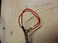
I used a very similar sniffer loop to the one in your picture rather than a direct connection, so I don't think I could have damped out any oscillation. There was unsurprisingly all sorts of stuff being picked up by the analyser, but I could find no signal that could be turned on or off by powering my circuit up and down.
I've given the board a thorough clean with Flux-Off and checked every component. The fact that the problem exists on both the right and left channels makes it unlikely that the problem is caused by a faulty component, although I did change the transistors in the CCS just to make sure.
I've given the board a thorough clean with Flux-Off and checked every component. The fact that the problem exists on both the right and left channels makes it unlikely that the problem is caused by a faulty component, although I did change the transistors in the CCS just to make sure.

- Status
- This old topic is closed. If you want to reopen this topic, contact a moderator using the "Report Post" button.
- Home
- Amplifiers
- Tubes / Valves
- Mystery noise has got me baffled