I bought a pair of OPTs from ebay.
The guy told that he removed them
from an old german receiver which was powered by
single ended el84.
I found some problems.
1.
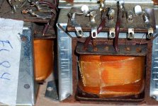
Unlike what I heard, it does not look like
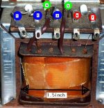
a SE one. I see seven wires around the
transformer. Yes, it looks like not a SE, but PP type
OPT with UL tap.
Well, it seems to be little bit small for PP because
the center area was just 1.5 inches.
2.
Two are thick, but the other fives are as thin as hair.
I wonder whether these hairy wires can hold signal
clearly.
_____________________________________________
SE?, PP?, Universal? Either way, I don't know how to
handle this.
The guy told that he removed them
from an old german receiver which was powered by
single ended el84.
I found some problems.
1.
Unlike what I heard, it does not look like
a SE one. I see seven wires around the
transformer. Yes, it looks like not a SE, but PP type
OPT with UL tap.
Well, it seems to be little bit small for PP because
the center area was just 1.5 inches.
2.
Two are thick, but the other fives are as thin as hair.
I wonder whether these hairy wires can hold signal
clearly.
_____________________________________________
SE?, PP?, Universal? Either way, I don't know how to
handle this.
Attachments
Perhaps not a mystery
Hi zxx123
I think the transformer is for single ended use, and if equipped with 7 taps, the following construction:
Winding 1: Primary with 1 tap, like a UL-winding, let´s say tap a,
b and c;
tap a: to EL84´s anode
tap b: (nearer tap c on the winding) input +V from PSU
tap c: output for EL84 screen grid(in pentode mode)
and driver tube(s) +V voltage(s)
With other words, anode load Ra (5,2kOhm) between
tap a and b, between tap b and c you have a choke
for driver tube(s) +V including EL84´s screen grid
(see below)
Winding 2: Secondary, independent NFB winding
Winding 3: Secondary, independent loudspeaker out
A typical PS topology from the tube radio era:
Rectifier -> 50microF to GND -> to tap b, from tap c -> 1kOhm(normally 3W) resistor -> 50microF to GND -> EL84 screen grid and driver tube(s) anode resistor(s) with possible additional filtering between.
Cheers......Ole
Thank, However................
Thanks, helan!
However, I need more explanation.
1. As you can see, five of wires are thin
and two of wires (dark brown) are thick. Can you agree that
the two thick wires are secondary tabs for speakerout?
It will be easier if I know secondary ones.
(Even if you are not sure, just tell me YOUR THOUGHT.
I will do full responsibility of my own for test.)
2. Now, I know three of wires are anode, ul (for screen grid),
and B+ and two of wires are +/- of speakerout.
How about the remaining two wires of them? It sounds like
they are winding 2: Secondary, independent NFB winding.
Right?
3. Do you know how I examine what are tab a, b, and c among tabs?
Is there any resistance value difference among those tabs?
4. Can I use the OPT without three (one UL & two NFBs) of those seven wires
Attachments

zxx123 said:1-2 513
1-3 512
2-3 48
Are you sure about those?
Kirchhoff would find that interesting.
- Status
- This old topic is closed. If you want to reopen this topic, contact a moderator using the "Report Post" button.
- Home
- Amplifiers
- Tubes / Valves
- Mysterious Output Transformer....