Hi, I'm just getting started with speaker measurements and I am getting this glitch in impulse measurements that is driving me crazy. If anyone can help me locate the source of the problem, I would really really appreciate it. Here are the details, and an image. I would be more than happy to post images of the results of any suggestions. Thanks.
Basic Setup is:
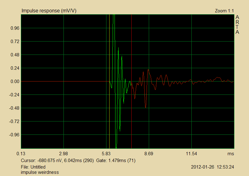
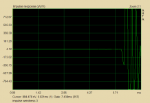
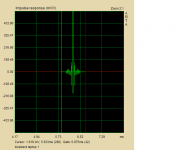
Problem is this little dip at the start of the impulse:
(please ignore the short reflection time - this is just an example of the dip)
Things I have tried with no change to the dip:
Any ideas?
Basic Setup is:
- Dayton EMM-6 mic with calibration file
- Lexicon Lambda USB interface/soundcard/preamp
- mediocre PC laptop with ARTA and HOLMimpulse
- single woofer(s), in boxes or on baffles, no crossovers or other components
Problem is this little dip at the start of the impulse:
(please ignore the short reflection time - this is just an example of the dip)
Things I have tried with no change to the dip:
- three totally different drivers
- two amps
- all sorts of different signal and measurement types/settings
- reversing electrical and digital phase (dip still goes down relative to pulse)
- different in/out channel combinations (although I've only got two channels)
- wide variety of measurement distances and angles (did notice the dip becomes a little jagged far off-axis, but remains present)
- suspected input pass-through on the Lexicon might be to blame, since it does not seem to be switched off - only resistively blocked with a pot. I believe I've located it's influence by adjusting levels, and it appears around 1ms before the real impulse and hardly above the electrical noise floor.
Any ideas?
Attachments
Hard to diagnose exactly but there are a few possibilities:
Might be the actual starting shape of the impulse response of the unit.
Might be a little electrical bleed through between measuring system output and input.
Most measuring systems have internal filtering (anti-alliasing filtering) and it could be connected to that.
Have you tried an output to input loop through or test of a wideband electrical device, to see what its impulse response looks like for the system alone?
Its not something I would lose too much sleep over (but I understand it bothering you).
David
Well, I thought I'd ruled out the first two by trying 3 drivers and by identifying a small impulse earlier in time that I figured to be the bleed through, but... I don't know? Someone just suggested in my other thread that I add a low-pass and see what happens to it, which I'll do.Hard to diagnose exactly but there are a few possibilities:
Might be the actual starting shape of the impulse response of the unit.
Might be a little electrical bleed through between measuring system output and input.
Most measuring systems have internal filtering (anti-alliasing filtering) and it could be connected to that.
As for the filtering, do you mean in the measurement software, the drivers, or the Lexicon hardware, or any of them?
No, I haven't. I am not clear on how to loop the Lexicon unit to back to itself to measure that, if it's possible. Do I need to rig up some components outside of it? When I first got it, I tried connecting a line output to the the other channel's line input, and it promptly stopped working and needed to be powered down. I figure something went into oscillation in there.Have you tried an output to input loop through or test of a wideband electrical device, to see what its impulse response looks like for the system alone?
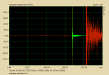
edit: Oh hey, I do have this image, though. I had the input and output on the other channel, so what you see here is actually a teeny version of output signal, followed/disrupted by a teeny version of the mic input (both bleeding into the disconnected channel that is shown here). I had another one without the mic input, and that shape the first arrow is pointing to tapers down to nothing in a linear / cone-shaped fashion.
Attachments
Last edited:
On further reflection:
Electrical bleedthrough is out because it happens after the air path delay rather than at zero time.
Can we see an impulse with no truncation on the front half?
By filtering I was thinking primarily the FFT program: Holm. Not sure what the Lexicon is dong but it more likely has an analog low pass.
Were you saying that with the woofer connected in either polarity that the waveform starts with the little downward hitch? i.e. whether the primary woofer impulse goes up or down the initial hitch is always downwards? This would be a good clue.
Its still possible that the true woofer impulse starts downwards initially and then reverses.
A straight through test will show you the measuring system impulse response. Connect output to input and measure. Be careful of levels. The measured impulse should be clean and relatively ring free. (pre-ringing and post ringing are possible)
David S.
...
A straight through test will show you the measuring system impulse response. Connect output to input and measure. Be careful of levels. The measured impulse should be clean and relatively ring free. (pre-ringing and post ringing are possible)
David S.
+1
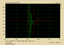
You mean with the entire measurement period included? Coming up.Can we see an impulse with no truncation on the front half?
edit: sorry I misread you: NO, it always goes the same way relative to the primary impulse. I though maybe it could be DC or something, which I don't think really makes sense, but I flipped the woofer polarity and the whole impulse flips, hitch and all, so when I invert the input, it's back to the exact same impulse as before swapping woofer polarity.Were you saying that with the woofer connected in either polarity that the waveform starts with the little downward hitch? i.e. whether the primary woofer impulse goes up or down the initial hitch is always downwards?
A straight through test will show you the measuring system impulse response. Connect output to input and measure. Be careful of levels. The measured impulse should be clean and relatively ring free. (pre-ringing and post ringing are possible)
Like I said, I think the Lexicon freaks out when I do that, but I'll give it another shot, as I haven't tried since the day I got it and maybe I was confused about something.
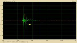
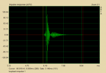
Also, here is the impulse with a 2mH series inductor on the woofer (attached).
Attachments
Last edited:
Repeat one of your measurements with the woofer polarity flipped (best to do both measurements together: 1 with normal polarity and one with flipped polarity).
I see from your woofer-with-inductor impulse that you have quiet preceeding the start of the impulse. It really does start by going downwards. That still might be normal, although I would think the inductor would have rounded it off.
David
I see from your woofer-with-inductor impulse that you have quiet preceeding the start of the impulse. It really does start by going downwards. That still might be normal, although I would think the inductor would have rounded it off.
David
I've done that, it flips the whole graph, 1:1 match.Repeat one of your measurements with the woofer polarity flipped (best to do both measurements together: 1 with normal polarity and one with flipped polarity).
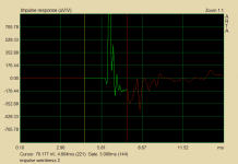
Well, I have quiet if I don't check "center impulse peak" before measuring in ARTA (see first attachment), but if I do check that (see 2nd attachement), there is a thing. If I zoom in, it's the same as the main impulse, dip and all, much lower in magnitude. I figure this must be the bleed through from the direct output of the mic. It's over 60ms back, though.I see from your woofer-with-inductor impulse that you have quiet preceeding the start of the impulse. It really does start by going downwards. That still might be normal, although I would think the inductor would have rounded it off.
Attachments
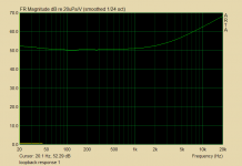
Okay so I hooked an output to an input, set the levels to well below any clipping, ran the usual impulse measurement, and got what's below. I then used that to make this rather disturbing frequency response plot... I forgot to remove the gating when I copied the frequency response plot, but it is the same ungated. EDIT: whoops, forgot to turn off the mic calibration, gotta do that over. EDIT2: okay fixed, same response curve, but smooth without the mic calibration applied.
Attachments
Last edited:
I thiiiink ARTA only allows for one response calibration file, so I would have to combine the above response with the mic response and load that. HOLMimpulse has separate settings for mic and system response. I don't know that I can even get either program to use the crappy sigmatel chip in the laptop, but I can try.
Here's the laptop loopback. It's flat as a frequency response. It seems like something is definitely wrong with the Lexicon here... I have made some recordings with it that sound just fine, although I would not necessarily have noticed the rising response (if that's real) in what I have recorded.
I'll try the Lexicon loopback in HOLM in minute, although that's what crashed it the first time.
I'll try the Lexicon loopback in HOLM in minute, although that's what crashed it the first time.
Attachments
- Status
- This old topic is closed. If you want to reopen this topic, contact a moderator using the "Report Post" button.
- Home
- Loudspeakers
- Multi-Way
- Mysterious Impulse Measurement Problem