Link to pics of a MyRef Rev E build in an off-the shelf 8Audio Anodized aluminium case from EBay:
http://www.diyaudio.com/forums/chip-amps/79303-chip-amp-photo-gallery-202.html#post2833888
http://www.diyaudio.com/forums/chip-amps/79303-chip-amp-photo-gallery-202.html#post2833888
The 8Audio case looks interesting, but there are no photos of how you organized things inside the case.
My concerns are mostly about passing close to the transformer with cables, particularly input ones, and having hum induced.
Would it be a good idea to place the heatsink on the outisde?
My concerns are mostly about passing close to the transformer with cables, particularly input ones, and having hum induced.
Would it be a good idea to place the heatsink on the outisde?
If your input cable is arranged to have a low loop area and it is twisted to offer + & - cancellation of interference then you can run input cables very close to transformer and such like components with no increase in interference.
It is circuits laid out on a flat PCB that inevitably have non canceling loop areas that are susceptible to picking up interference.
If the input cables are of very high sensitivity eg, microphone and Vinyl cartridge then adopting screened twisted pairs are usually enough to enhance interference rejection to an acceptable standard.
Then you have screened twisted quad and screened balanced impedance connections for the really severe situations.
Note, I have deliberately not included coaxial cables for audio signal interference attenuation.
The 8Audio case looks interesting, but there are no photos of how you organized things inside the case.
My concerns are mostly about passing close to the transformer with cables, particularly input ones, and having hum induced.
Would it be a good idea to place the heatsink on the outisde?
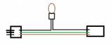
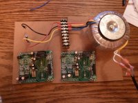
The input cables are shielded coax and run by the right side-panel of the case, while the trafo is at the left-rear with AC1-0-AC2 cables to the boards at the centre.
I've triple-braided the AC1-0-AC2 cables from the trafo to minimize the enclosed radiating loop, but the bigger problem is leakage flux from the EI laminations. It's fairly quiet now, but it can be made even darker by upgrading to an R-core trafo later.
Regarding the screened twisted pair - would the outer shield be grounded to the chassis ground or PGND? PGND is noisier, so that's not a terribly good idea. Chassis ground (safety earth) seems reasonable.
What's the point of it (not including them as an option)? Isn't a coaxial as good rejecting garbage as a shielded twisted pair (not balanced)?Note, I have deliberately not included coaxial cables for audio signal interference attenuation.
Thanks,
Regards
Here is a link to the results of adding the LF01 to my top MyRef build.
http://www.diyaudio.com/forums/chip-amps/54571-my-audiophile-lm3886-approach-340.html#post2835237
http://www.diyaudio.com/forums/chip-amps/54571-my-audiophile-lm3886-approach-340.html#post2835237
Regi,
I started back in the 70's by sending low level signals down coaxial cables. I stuck with it because I did not know any better. It worked for TV and for Radio, everybody used it. It was only in the 80's I discovered screened pair (but not twisted) that there are other ways. Now I almost exclusively use twisted pair and twisted quad, both unscreened. They seem to perform better. They are easier to terminate. They are easier to route/shape. They are cheaper. They are colour coded.
They are not balanced impedance connections.
Last edited:
Can a polyprop be used in place of the 100nf polyester at C4 & C5?
Sure, even better.
Pay attention... they should be 100V rated.
Pay attention... they should be 100V rated.
Thanks. What is the maximum voltage at c4 and c5?
I have some polyprop for C10 too.
Why 100V.
The maximum differential voltage across any component is ~+ve rail to -ve rail, i.e. ~70Vdc.
Only if some oscillation is allowed to happen can the rail voltages be exceeded.
You're right, Andrew.
The differential voltage is 70V, so a 63V rated cap is not enough. The next rating step is usually 100V.
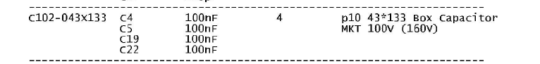
I've attached also an excerpt from Mauro's original BOM where 100V rating is clearly stated.
Attachments
Do C4 and/or C5 have the full 70V across them?
C4 has 70V DC for sure since is the rail to rail decoupling cap of LM3886PS, C5 also have 50V AC since it's between secondaries, in both case a 100V DC rated cap is needed, isn't it?
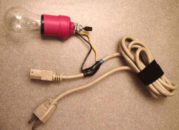
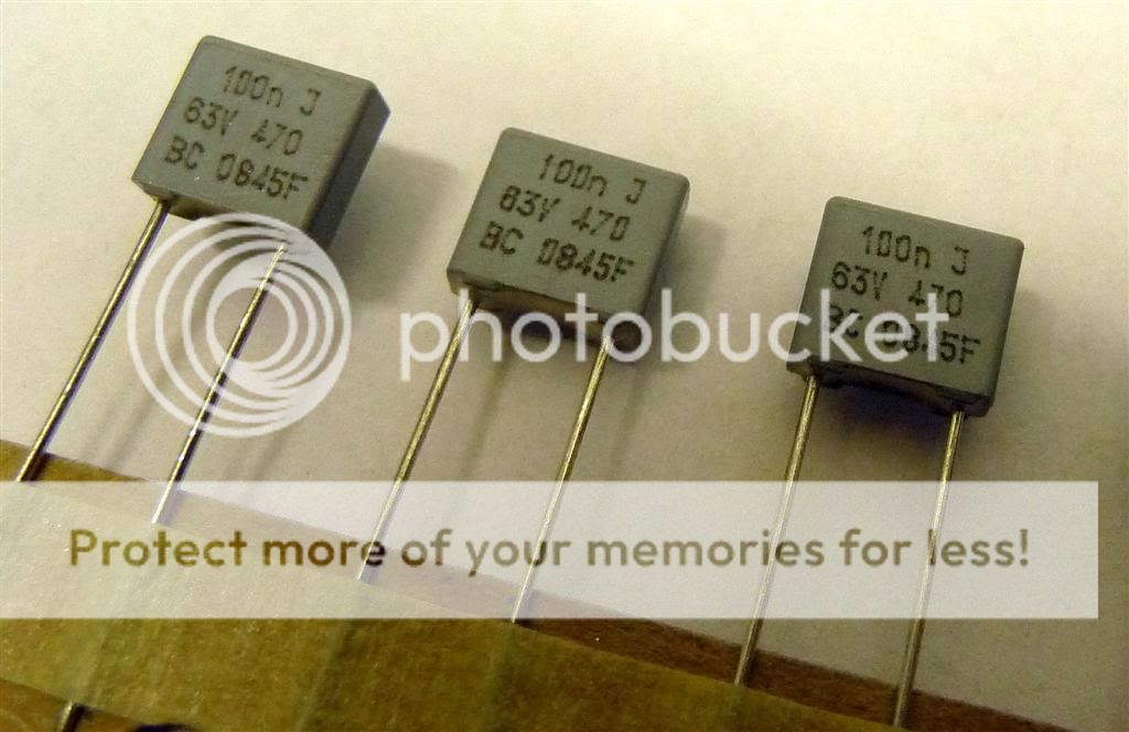
I cant identify these 100n caps. Would anyone be able to help?
Can a polyprop be used in place of the 100nf polyester at C4 & C5?
Those are 100nF/63V/5% BC (now Vishay-BC) Polyester (most probably). MKP polypropylene will definitely be better for C4, and probably C5 too. You'll need at least 100V, and preferably 250V rating for both.
Yet Another MyRef Build.
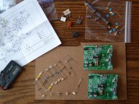
Since it's not yet making music, I figured I would post some pics here rather than the ChipAmps gallery.") . These are two of Siva's RevC boards with his RevE component package. The first couple photos show the assembly and testing of the power section and delayed turn-on circuit, followed by the completion of the rest of the kit components. I need to get my order in for the big caps and LM3886s - I have a few in my "reclaimed" bin, but they look a bit rough and I'd prefer to use fresh pieces for the initial build.
. These are two of Siva's RevC boards with his RevE component package. The first couple photos show the assembly and testing of the power section and delayed turn-on circuit, followed by the completion of the rest of the kit components. I need to get my order in for the big caps and LM3886s - I have a few in my "reclaimed" bin, but they look a bit rough and I'd prefer to use fresh pieces for the initial build.
The kit was complete and reasonably documented. I had to send a couple emails to Siva to get clarification on what certain components were (it's been a while since I did a kit) but he responded quickly and with full answers in both cases.
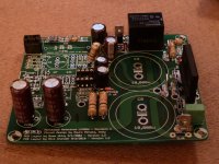
BTW, does anyone have a good recommendation of soldering/connection methods for those two 10,000 uF caps? I was looking at getting a set of snap-in's over at ApexJr.com, but the holes are so large I was worried about how to get a good solder connection. Thoughts?
Thanks,
-bill
Since it's not yet making music, I figured I would post some pics here rather than the ChipAmps gallery.
. These are two of Siva's RevC boards with his RevE component package. The first couple photos show the assembly and testing of the power section and delayed turn-on circuit, followed by the completion of the rest of the kit components. I need to get my order in for the big caps and LM3886s - I have a few in my "reclaimed" bin, but they look a bit rough and I'd prefer to use fresh pieces for the initial build. The kit was complete and reasonably documented. I had to send a couple emails to Siva to get clarification on what certain components were (it's been a while since I did a kit) but he responded quickly and with full answers in both cases.
BTW, does anyone have a good recommendation of soldering/connection methods for those two 10,000 uF caps? I was looking at getting a set of snap-in's over at ApexJr.com, but the holes are so large I was worried about how to get a good solder connection. Thoughts?
Thanks,
-bill
Attachments
Last edited:
BTW, does anyone have a good recommendation of soldering/connection methods for those two 10,000 uF caps? I was looking at getting a set of snap-in's over at ApexJr.com, but the holes are so large I was worried about how to get a good solder connection. Thoughts?
It's unlikely you will be able to fill the hole with solder if it's too large.
For the caps I'd put solder first on both sides, and then, with the solder still hot to touch, I would bend the cap pins to secure them firmly. Then apply the solder. The idea is to provide a mechanical support first that will hold the cap to the pcb, and then solder.
Putting solder first is done in order to the capacitor not getting too hot.
Good luck.
Carlos
- Status
- This old topic is closed. If you want to reopen this topic, contact a moderator using the "Report Post" button.
- Home
- Amplifiers
- Chip Amps
- MyRefC build guide