I bought my k71-4 caps from valtek. The shipping was reasonable and fast to the US. I bought two sets and they were very closely matched. The set that I am using for the FE build measured .999uf and. 998uf. They measured the same after soldering tooI am hoping to have some listening impressions soon.
Soil,
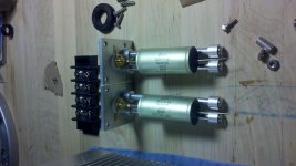
Tell us about the mounting system for the K71s. Rods?
Jac
2% is good ? He has lot of 4 with 5% though.
By the way, if you have a question or want something a little different from what is on offer, just email valtek. For example, if he had 4 of the 2% K71-4s and that's what you wanted, he would quote you a price. Also, he is fairly smart about Russian caps and the differences, so ask away.
Jac
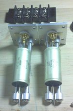
Jac, my original plan for the enclosure had the k71s in the position that they occupy, but that created a mounting issue. I wanted to have a somewhat modular design that would easily allow swapping in the future if the opportunity arose. My original plan was to "machine" some plate to make an unnecessarily complicated part to mount the caps, but I went a different direction. I decided to browse my local hardware store (the type that has a "real" selection of fasteners) and see if I could come up with a solution. Aside from the mounting plates that I made from 1/8" aluminum (with a template) the rest of the construction that you see in the pic is available any time at the hardware store. These consist mainly of aluminum tube, threaded internally, an aluminum spacer of a larger diameter, a copper washer and a few stainless fasteners.
I wanted to easily be able to duplicate these if I changed caps, and be able to easily remove them. I saved the template for the mounting plates if the need arose. In the attached pic you can see how these are removable as a unit without disrupting too much internally.
I am only hours from being finished, and I could have been today.......but it was nice out so I hung some new lighting in my garage/shop......soon
P.s. the crayon on the table is not part of the design, it is an early work of my four year old and the envy of my 17 month old.
Attachments
Last edited:
.......Aside from the mounting plates that I made from 1/8" aluminum (with a template) the rest of the construction that you see in the pic is available any time at the hardware store.......
I am only hours from being finished, and I could have been today.......but it was nice out so I hung some new lighting in my garage/shop......soon
Will,
Beautiful work!! And a really interesting way of approaching it that I've never seen. Of course, there is lots I haven't seen, but still great. Isn't it wonderful what a good hardware store can do for you?
Sometimes, the weather just calls to you. Congrats on the amp build. I can't wait to see the finished pictures.
Jac


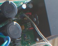
I like the way the caps mounting looks, but I can't imagine it does anything beneficial to sonics. I hope this isn't too harsh, but unless those rods are supported at both ends, they'll probably vibrate, which is the worst thing you can do to a cap. I think there should be some sort of damping material between the metal caps casing and the metal rods. It appears the input wiring is excessively long and routed near power supply wiring and circuits, which might contribute to noise despite the beautiful twisting. I'm not really into sharp 90 degree bends and perfectly straight lines of wire, either.
It does look really cool, though, if you plan to sit and look at your amp's internals. There is something to be said for orderly layout, but it should never be at the expense of sonics. I don't know if this construction will contribute to any degradation of signal, but it will almost certainly not yield improvements. Sorry for being so negative, but I don't think other builders should be inspired by this layout only because of its appearance.
Peace,
Tom E
Thanks guys, this has been a fun build. I did manage to finish the wiring of one channel tonite and will hopefully finish the other tommorow. I will have some sonic feedback soon.
I started out with a solid plan for the entire build, but as all projects go I made improvements as I went. With each improvement I made, I thought of another improvement that I could make that went into the next time column. hopefully all of these "design" choices dont negatively affect the sonic qualities of this amp...we will see.
Thanks for the better pose Bob, sorry about your neck.....
I started out with a solid plan for the entire build, but as all projects go I made improvements as I went. With each improvement I made, I thought of another improvement that I could make that went into the next time column. hopefully all of these "design" choices dont negatively affect the sonic qualities of this amp...we will see.
Thanks for the better pose Bob, sorry about your neck
.....Tom, I appreciate your comments as some of them play to my questions about how this amp will sound. The mounting of the caps is solid and will not be any more prone to vibration in this setup then if they were mounted to the pcb. As for the wiring, the length of the wire is only a small distance greater then if the crows path was taken. It is difficult to route the signal wiring away from power wiring in this amp because of the board layout. other builders seem to have had success. I did try to keep as much ac shielded from the inside of the amp.
why are you not into straight wire and 90 degree bends? I know 90 degree bends are not recomended on pcbs, but why not here?
why are you not into straight wire and 90 degree bends? I know 90 degree bends are not recomended on pcbs, but why not here?
What is far more important is that the Signal Return MUST FOLLOW as closely as possible the Signal Hot throughout the whole route........... It appears the input wiring is excessively long and routed near power supply wiring and circuits, which might contribute to noise despite the beautiful twisting. ...........
If the Signal Hot comes in at one end of the cap and out at the other end, then the Signal Return must do exactly the same.
Q.
What effect would splitting the signal return into two wires at the cap input end do?. Then run the two wires at 180degrees diametrically opposed for the length of the cap and then rejoin to become one wire at the other end.
Would this help cancel the antenna effect of the single return that is separated from the signal hot that effectively runs down the centroid of the cap?
The signal hot and return are equal lengths for both channels. The wire for the hot channel is shorter to acount for the length of that cap and its leads. They are both twisted where layout would permit. The input hot and ground are not as far apart on the pcb as the outputs so there is less untwisted in the routes. The total length of the runs amounts for the furthest distance from the input to pcb.
I don't know yet if there will be a noise issue, it could go either way. If there is I will change it. In my previous amp I used the same wire and had parallel runs with 90 degree bends and no twisting with no issue.
I don't know yet if there will be a noise issue, it could go either way. If there is I will change it. In my previous amp I used the same wire and had parallel runs with 90 degree bends and no twisting with no issue.
What is far more important is that the Signal Return MUST FOLLOW as closely as possible the Signal Hot throughout the whole route.
If the Signal Hot comes in at one end of the cap and out at the other end, then the Signal Return must do exactly the same.
Q.
What effect would splitting the signal return into two wires at the cap input end do?. Then run the two wires at 180degrees diametrically opposed for the length of the cap and then rejoin to become one wire at the other end.
Would this help cancel the antenna effect of the single return that is separated from the signal hot that effectively runs down the centroid of the cap?
I think Will has done better than I have at the signal and return routing, keeping them the same length and path. I'll have to rethink my plan. Of course, he is way ahead by having an enclosure at all.
Andrew,
Regarding your two wire return idea, I like it intuitively. I don't have any knowledge in the area of antenna theory, so my liking it has little weight, but it seems it seems right.
Jac
Will,
If you've successfully used this same configuration before, then my concerns have little merit. I don't make any claims to expertise in these matters. You have obviously put a lot of thought and effort into your build, and I hope your amp sounds as good as it looks. I'd like to see if the outside looks as nice, when you have a chance to post pics.
If you do get any noise from your input lines, you might try grounding that metal cap casing (or, conversely, insulating it if it's grounded to the enclosure by those rods), assuming there is no continuity of the case to the positive signal path.
In my own layout, the amp input is an inch or two away from the source (active xover in the same enclosure), so lead configuration seems to make little difference. I have taken no care whatsoever at twisting them or even keeping them close to each other, but they are similar in length. I am not setting a good example, but noise is absent. Perhaps small loops and minor differences in length aren't critical, at least if they're in "quiet" sections of the enclosure. I do, however, avoid putting line level signal carriers near power supply wiring and circuitry.
I try to not sharply bend any kind of wire in any application at 90 degrees; if nothing else, it certainly puts less stress on the metal. I like curves, and I avoid parallel runs of high and low current whenever possible.
Peace,
Tom E
I do have some concerns about possible noise from the transformer secondaries due to their location. I figure if it is present I have two options; one, I can try to shield the secondaries, or two, I can flip the faston mounts on the pcb and mount the secondaries from the bottom. I should have done this from the beginning, but they had been long soldered to the board before this occurred to me it may be neccesary surgery though!
I will post some full pics later today and maybe listen to some music too.
it may be neccesary surgery though!I will post some full pics later today and maybe listen to some music too.
I use sockets for small components and fastons for really big caps. Madisonears hates the fastons, but I think it works for selecting components. Of course, when finally soldered in, there is an improvement in sound. I agree with Dario, Bob, et al, that these temporary connections are good enough to hear most of the amp character and are good enough for selecting components.
Here is a massive zoom showing C9 with a BG PK in sockets. The picture quality isn't so good, but hopefully you get the idea.
http://www.diyaudio.com/forums/attachment.php?attachmentid=339223&stc=1&d=1364581703
Here is a massive zoom showing C9 with a BG PK in sockets. The picture quality isn't so good, but hopefully you get the idea.
http://www.diyaudio.com/forums/attachment.php?attachmentid=339223&stc=1&d=1364581703
Attachments
Sockets are much smaller than fastons and you can use them for most of the caps in an FE. I'm not sure if the picture was good enough for you to see the sockets on the board near the bottom center of the picture. The sockets are soldered and the BG PK leads are just pushed into the sockets. The sockets work for through hole resistors and all but the biggest caps. Sometimes, you get to file the ends down to a point.
571-1-1571994-0 IC & Component Sockets | Mouser
If you look at the first page of the FE group buy, the amp that Dario has pictured appears to be using fastons for the True Copper in C13.
For surface mount components, there is low temp unsoldering solder, but I just took advantage of Dario's experimentation and followed his suggestion.
SMD16 Chip Quik | Mouser
You probably already know about solder wick, but I didn't when I started this process and it is my new best friend when I do have to unsolder something. Learning about that and tacky flux for soldering SMD parts was a huge help.
It is a problem without a perfect solution, so good luck with whatever you decide.
Jac
- Status
- This old topic is closed. If you want to reopen this topic, contact a moderator using the "Report Post" button.
- Home
- Amplifiers
- Chip Amps
- My_Ref Fremen Edition RC - Build thread