Well I am finally soldering up the boards.
Hi Paul,
fine
")
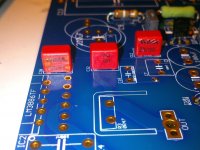
A quick question though. C12 is not a polarized cap correct? That being said is there a preferred installation? I have the Amtrans 73778.
Exaclty, C12 it's not poalrized so it works whatever direction you mount it.
Though there's a preferred (best sounding) direction.
For both FKP2s and Amtrans you should use silkscreen markings which have same direction of markings on caps:
In looking at the schematic, polarized cap installations are clearly marked with a + as is the circuit board. However, I noted o's on some of the other cap diagrams on the board. What is this?
Which diagrams?
On resistors direction is indicated by a '>' mark.
Clearly a newbie here.
Absolutely not...
resistors and caps orientation is a controversial argument and an extreme optimization.
Attachments
Got clicks, lights and music - Hoorrayy
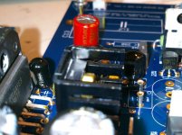
Both amps are on line and producing good sound. It was not without some prodding however.
At first power-up -with a dim bulb tester- both relays worked and the LEDs lit. One module had DC offset of 11 mV, but the other was .5V. At that point I hadn't completed the normal thorough cleaning of the bottom of the PCB. When I started that process I found a few substandard solder joints. A small piece of lead trimming fell off and I don't know if it was shorting something or not. But that final cleaning step is as important as any other part of the build.
On reassembly both amps are reading ~ 11 mV and there is no sign of hum or distortion. These builds are a combination new top choice parts, some from the economy BOM and a handful of leftovers from previous projects. It will eventually become the reference build.
I'll let them ferment for a few hours , run a couple passes of the Isotek CD and report back later today.
Attachments
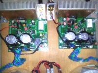
Thanks guys. I did the build step by step following Dario's guide posts at the top of the thread. Can't think of anything I could add or change as it is straight forward and logical. A couple mistakes I made were easily reversed by using the Chip-Quick alloy - great stuff.
Jac already posted about the hole size for D4 and a little filing of the leads takes care of that. Compared to the beta all the multiple pad arrangements are a blessing for using Caddocks with or without sockets. Dario, it might be a good idea to put the Mouser numbers for the sockets and the posts for C13 somewhere on the BOM. I soldered the Sonicaps temporarily because I only had three of the double lead fastons I could modify to fit.
I'm really looking forward to the reports of trials, tests and part suggestions from all the RC builders.
P.S. To save a few dollars I chose Johnson solder this time. Was very eaay to work with.
Attachments
Last edited:
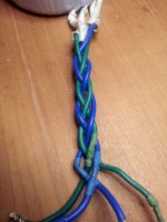
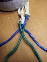
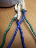
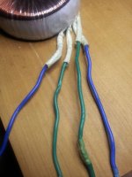
how did you twist the transformer lines going to the board?
I happen to know that Bob REALLY likes twisting wire.
Good to see another successful build.
Peace,
Tom E
1. One color inside, other outside.
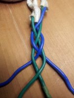
2. Cross outside blues over inside green to form an X.
3. Left green outside over, then right green over to make another X inside the blue one.
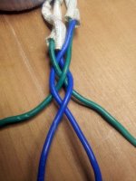
4. Stay consistent by always starting the next crossover with the left outside color first and then bringing the right outside over last.
5. Stretch and wiggle as you proceed to get the tightens and uniformity you desire.
Complements of Hap from the craft cabin, Camp Iroquois, Oscoda, Michigan - a lifetime ago.
2. Cross outside blues over inside green to form an X.
3. Left green outside over, then right green over to make another X inside the blue one.
4. Stay consistent by always starting the next crossover with the left outside color first and then bringing the right outside over last.
5. Stretch and wiggle as you proceed to get the tightens and uniformity you desire.
Complements of Hap from the craft cabin, Camp Iroquois, Oscoda, Michigan - a lifetime ago.
Attachments
Andrew, as this stuff was easy to use, it is thicker than I would have preferred - but that didn't cause too much of a problem. Somebody reminded me I needed to pay the light and water bills so I was looking for something acceptable I could buy in small quantities and include it in an existing order. Sonicraft and others sell good stuff by the foot but I'm tired of paying for the college education of the UPS man's daughter.
Next time I'll shop around. Also want to get a more sophisticated solder station soon.
Next time I'll shop around. Also want to get a more sophisticated solder station soon.
Last edited:
Good news today, I've two channels sound!!!
One channel still has 30mV DC offset, but it's stable and sound!
So, I suppose, any component is burned.
CONGRATULATIONS! That was a struggle.
Can you hear any differences at all between the channels? A mono source and swapping the speaker leads might show something.
Glad you stuck with it.
PS. One thing I forgot to mention yesterday was the amp that had an initial .4V DC offset had a full second delay before the relay activated. Now they are simultaneous. Don't know if that is at all helpful.
Last edited:
Here is one for the FE builders with labs and test equipment. It would be fun and interesting to see if we can fill in the blanks for this amp.
Took this from a big manufacturers blurb.
...........
Continuous power output:
250 watts RMS x 2, 20 Hz - 20 kHz, 8 Ω, all channels driven
400 watts RMS x 2, 20 Hz - 20 kHz, 4 Ω, all channels driven
750 watts RMS x 1, 20 Hz - 20 kHz, 8 Ω
Current capacity:
60 amperes peak per channel
Power bandwidth:
5 Hz - 100 kHz, +0/-3 dB at 1 watt
Total harmonic distortion:
< 0.2 % at full power
IM distortion: balanced 16 V rms
< 0.04 %
Slew rate:
> 130 V/µsecond
Dynamic headroom:
> 1.5 dB
Interchannel crosstalk:
> 80 dB at 1 kHz;
> 63 dB at 20 kHz
Input sensitivity:
1 V for 28.28 V, THX Reference Level
Input impedance:
33 k Ω unbalanced; 66 k Ω balanced
S/N ratio:
112 dB, input shorted, IHF A-weighted
Damping factor:
> 1100 at 20 Hz
Voltage:
110V - 120V
Dimensions:
17-1/4" w x 7-5/8" h x 19-1/8" d, 7 " h without feet
Net weight: 60 lb.
...............
Attached is a PDF for anyone interested.
Attachments
Good news today, I've two channels sound!!!
One channel still has 30mV DC offset, but it's stable and sound!
Great news.
Let's see if the DC offest, after burn-in and cleaning (if you dind'nt already), normalize.
Here is one for the FE builders with labs and test equipment. It would be fun and interesting to see if we can fill in the blanks for this amp.
Yes it would be interesting but I think it's a bit misleading to post typical values from a different amp..
BTW I don't expect great variations from Mauro's declared performance for the My_Ref:
Bandwith (tipical): 2Hz-70Khz
Output power(±37V): 40W/8ohm – 56W/4ohm
Damping Factor (8ohm): >200 (frequency and compensation dependent)
S/N 600ohm: >90 dB (compensation depended)
THD e IMD (tipical), 20Hz-20Khz, 1-40W/8ohm: <0.05%
Hey Dario,
Sorry, I just grabbed something with a lot of entries as a template, There was no comparison implied or intended. I should have followed my thought to erase the values. But I'm sure you are aware my key is what one hears and the data is, IMHO, secondary. It could be a fun sideline project that aids in the fine tuning of the final boards.
Sorry, I just grabbed something with a lot of entries as a template, There was no comparison implied or intended. I should have followed my thought to erase the values. But I'm sure you are aware my key is what one hears and the data is, IMHO, secondary. It could be a fun sideline project that aids in the fine tuning of the final boards.
Yes, it would be nice if all manufacturers would publish a full set of specifications.
But even that set, misses information.
Like 1r0 and 2r0 performance, even if limited to just a 1minute,or so, test.
like a real dynamic headroom stating the test condition.
like a real noise output without weighting.
like real output impedance at a variety of audio frequencies.
And why is power bandwidth quoting 1Watt? -3dB for the power bandwidth should be outputting 125W into 8r0.
Last edited:
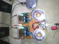
Before you guys try to politely explain the correct direction for a heatsink, let me explain that my final application of these boards will be mounted vertically on the back of each speaker. ........
Jac, I don't want to get anywhere near a "Cable Wars" discussion, but how far apart will your speakers be and what will you be using as interconnects?
I'm considering a similar arangement.
My Big Project
Hi Bob,
No cable wars required.
My speakers are about 11 feet (about 3.3 meters) apart. Currently, my amp is centrally located and I am using single ended (RCA) connections with some normal length interconnect cables that I made from Belkin cable and ends I bought on MCM. My speaker cables are of the "nothing special" type.
The FE amps are part of a larger project for me that converts the analog part of my system to balanced connections except for the last few centimeters from the FE output to the speaker input. I designed up a small board as a balanced line receiver using AD797 op amps which will be mounted next to the FE's and convert the balanced signal to single ended as input to the FE.
I also built a DIY pre-amp that is called Reliaxed 2 that is balanced all through. I still have to redesign and build my subwoofer control board so that it accepts balanced input and design a balanced crossover between the satellites and subwoofer. Naturally, all interconnects, including the run from the satellite output to the FE's mounted at the speakers, will be balanced interconnect cable. I will probably use Mogami star wire.
The advantage of the balanced approach it is more immune from noise than single ended and doesn't combine the signal return current with the grounding circuit. I have a friend who buys used high-end audio (Sterophile kind of stuff) for his system. He tells me that the change from single ended to balanced was a worthwhile step in sound for him.
Anyway, a very nice sounding system can be done with single ended, so this project is mainly a learning experience for me. Unfortunately, the big difference here is balanced .vs. single ended, rather than the amps close to the speaker, so my reasons probably don't help you.
The one thing I can say is that, if you could have the same signal and noise quality with the power amps near the source or at the speaker, I believe you get a marginal advantage having the power amps at the speaker. In theory, there is a small improvement in power amps ability to control/damp the speaker when closely located. That said, with a good power amp and speaker cables, that difference may be vanishingly small.
Jac
Jac, I don't want to get anywhere near a "Cable Wars" discussion, but how far apart will your speakers be and what will you be using as interconnects?
I'm considering a similar arangement.
Hi Bob,
No cable wars required.
My speakers are about 11 feet (about 3.3 meters) apart. Currently, my amp is centrally located and I am using single ended (RCA) connections with some normal length interconnect cables that I made from Belkin cable and ends I bought on MCM. My speaker cables are of the "nothing special" type.
The FE amps are part of a larger project for me that converts the analog part of my system to balanced connections except for the last few centimeters from the FE output to the speaker input. I designed up a small board as a balanced line receiver using AD797 op amps which will be mounted next to the FE's and convert the balanced signal to single ended as input to the FE.
I also built a DIY pre-amp that is called Reliaxed 2 that is balanced all through. I still have to redesign and build my subwoofer control board so that it accepts balanced input and design a balanced crossover between the satellites and subwoofer. Naturally, all interconnects, including the run from the satellite output to the FE's mounted at the speakers, will be balanced interconnect cable. I will probably use Mogami star wire.
The advantage of the balanced approach it is more immune from noise than single ended and doesn't combine the signal return current with the grounding circuit. I have a friend who buys used high-end audio (Sterophile kind of stuff) for his system. He tells me that the change from single ended to balanced was a worthwhile step in sound for him.
Anyway, a very nice sounding system can be done with single ended, so this project is mainly a learning experience for me. Unfortunately, the big difference here is balanced .vs. single ended, rather than the amps close to the speaker, so my reasons probably don't help you.
The one thing I can say is that, if you could have the same signal and noise quality with the power amps near the source or at the speaker, I believe you get a marginal advantage having the power amps at the speaker. In theory, there is a small improvement in power amps ability to control/damp the speaker when closely located. That said, with a good power amp and speaker cables, that difference may be vanishingly small.
Jac
- Status
- This old topic is closed. If you want to reopen this topic, contact a moderator using the "Report Post" button.
- Home
- Amplifiers
- Chip Amps
- My_Ref Fremen Edition RC - Build thread