Thank you Dabore84, but your explanation is what I also knew as thermal pads.
In his tutorial, it seems to me, Dario uses this term to indicate something else, that I can not understand or recognize.
Best regards
Giacinto
Hi Giacinto,
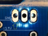
a pad in italian, in this context, is a 'piazzola'.
When you have a pad on a copper pour, as a ground plane, soldering to it is pretty difficult because you have to apply a big amount of heat since the pour acts as a heatsink.
A solution is to remove a bit of copper around the pad so that heat conductivity between pad and pour is lower.
This is a thermal (relief) pad.
More USB microsocope porn:

Attachments
Fresh build and DC offset
Hi,
I finished my build yesterday and after the first power on, the relay closed, but the board number 1 showed a DC offset around 90mV with input shorted, that didn't look right.. AC with input shorted was around 0.1 mV, which I think is OK. Given time, the DC values were going down, slowly but steadily.
For comparison, I removed board 1 and hooked up the board number 2 and it measured 8mV DC, but the AC readings were jumping up to 1mV occasionally. Which also wasn't right. I measured the reference voltages on both boards as depicted on the PCB and I think there were no big differences.
I'm only using a single 2x24VAC transformer, when measurements were taken, only a single board was connected at a time. The test points showed
Board 1:
Speaker output with input shorted:
DC: 44.5 mV
AC: 0.12mV
Testpoints:
-35: -33.8
-14: -13.98
-14.6: -14.59
-0.6: -0.593
1.25: 1.253
+35: +33.8
+14: +13.83
+14.6: +14.43
+0.6: +0.588
1.25: 1.253
Board 2:
Speaker output with input shorted:
DC: 8 mV
AC: 0.1 - 1mV jumping around
Testpoints:
-35: -33.6
-14: -13.89
-14.6: -14.45
-0.6: -0.593
1.25: 1.253
+35: +33.6
+14: +13.91
+14.6: +14.51
+0.6: +0.587
1.25: 1.254
I decided to put it in the case, nevertheless. Just to see if I could hear something strange when I hook it up. DC was higher than expected, but far from dangerous. I'm not saying it didn't bother me, it was out of spec for sure.
I didn't hear anything strange.
This morning I decided to measure the outputs again. To my surprise, now both boards were giving DC offset around 20 - 40mV... Hmm... I turned the amplifier off and on a couple of times while measuring with input shorted, floating and connected to the source. I decided to measure DC while playing music, with speakers connected and got values around 14mV on both channels. That's more like it. Although I have no idea how it came to be... It's been playing for 20 minutes or so... now Board 1 is @ 11mV DC, Board 2 is @ 6mV DC. I'm getting the same values with input shorted, open and connected to source.
Does this look OK to you all?
I do not have one hooked up to measure. Less than 10 me should be fine. The output relay will open up if it sees either dc or other faults.
I had a pad open up in the feedback loop once while playing music and got close to 30volts dc on the relay. Sounded like a cannon went off.
I had a pad open up in the feedback loop once while playing music and got close to 30volts dc on the relay. Sounded like a cannon went off.
Thanks Panelhead, the dc values went even further down, so I think it will be ok, although I'm curious why it started at 90mV and slowly went down to 8 which I measured yesterday.
Now another question, I hear a bit of sibilance and the sound being a touch too bright and I'm wondering if it has anything to do with my C9 choice. Couldn't find the recommended nichicon, nor elna cerafine or bg pk, so I ordered a 50V Silmic II, because it was mentioned in BOM. Does this cap need some kind of burn-in? And more imporantly, will it get any over time, given its position? In the meantime I ordered some BG PK from parts connexion, but I don't want to rush things, swapping caps before they get their chance to settle. In my standard lm3886, the local decoupling had influence on sibilance, I had 1000u, 22u and 4.7u and changing the 22u from Panasonic FM to Nichicon Muse shaved quite a bit off of sibilance...
Now another question, I hear a bit of sibilance and the sound being a touch too bright and I'm wondering if it has anything to do with my C9 choice. Couldn't find the recommended nichicon, nor elna cerafine or bg pk, so I ordered a 50V Silmic II, because it was mentioned in BOM. Does this cap need some kind of burn-in? And more imporantly, will it get any over time, given its position? In the meantime I ordered some BG PK from parts connexion, but I don't want to rush things, swapping caps before they get their chance to settle. In my standard lm3886, the local decoupling had influence on sibilance, I had 1000u, 22u and 4.7u and changing the 22u from Panasonic FM to Nichicon Muse shaved quite a bit off of sibilance...
I have found the Silmic to be the opposite of sibilance. Some feel they lose resolution. Beware of bogus BG caps. They have not been manufactured in a long time. Most for sale are whatever caps with BG sleeves.
I need to ask George Korga or maybe Dario a question. My new speakers are highest efficiency I have used. Gain structure is a little off matching with gain from dac to amp.
I would love to adjust the feedback loop to drop 6 - 10 dB of gain. I know all this is optimized for settling time, overload response, and stability. Will increasing the feedback cause issues.
One great feature is the dac and My_Ref are completely silent with no music playing. The noise floor is way down there.
We shall see... Dario pointed the parts connexion stock of 220uF/4V BG PKs out. And the asking price is low enough to give them a shot. The sibilance... it could be that it's in the recordings and whatever I was playing them on was masking it, who knows. Funny thing is it's not the amount, but the qualily of it, sounding kind of unnatural/synthetic. Anyway, a lot of things to try, a lot of music to listen to
the dc values went even further down, so I think it will be ok, although I'm curious why it started at 90mV and slowly went down to 8 which I measured yesterday.
Did you clean thoroughly your boards? If not it would be the most probable reason.
Now another question, I hear a bit of sibilance and the sound being a touch too bright and I'm wondering if it has anything to do with my C9 choice. Couldn't find the recommended nichicon, nor elna cerafine or bg pk, so I ordered a 50V Silmic II, because it was mentioned in BOM. Does this cap need some kind of burn-in? And more imporantly, will it get any over time, given its position?
Silmics will settle afetr 40-50 hours of use.
It's unlikely that they are the source of sibilance, as Panehead already wrote, usually they tend to smooth details.
I need to ask George Korga or maybe Dario a question. My new speakers are highest efficiency I have used. Gain structure is a little off matching with gain from dac to amp.
I would love to adjust the feedback loop to drop 6 - 10 dB of gain. I know all this is optimized for settling time, overload response, and stability. Will increasing the feedback cause issues.
Lowering gain would require major changes to compensation networks, this is something I'm not able to do.
Maybe George has a better answer.
Hi,
I kindly ask for a confirmation:
I read that Q1 (BC639-16) could be replaced by BD139-16.
Can Q2-Q3 (BC546cta) be replaced by BD140-16?
Here Mouser links
BD13916STU ON Semiconductor / Fairchild | Mouser Italia
BD14016STU ON Semiconductor / Fairchild | Mouser Italia
Thank you all
I kindly ask for a confirmation:
I read that Q1 (BC639-16) could be replaced by BD139-16.
Can Q2-Q3 (BC546cta) be replaced by BD140-16?
Here Mouser links
BD13916STU ON Semiconductor / Fairchild | Mouser Italia
BD14016STU ON Semiconductor / Fairchild | Mouser Italia
Thank you all
Dear George, all..
Unfortunately these days I live very high stress period, so cannot interact as much as I would like.
George's request is an interesting one, with the lm318 unfortunately I do not have good Spice results so the best would be build and measure..
It can be done but not right now..
I hope I can be back soon with something.
I owe George a big welcome back to the club..
I mean for the new experience with this old companion..
Also I would say: now we are talking, the dance sarts..!
Although i'm silent our little group and myself do advance with this beautiful amp.. (Evo, for me)
The same for Dan, i'm really sorry!
Ciao, George
Sorry to hear George
I also went through a rough period a few months ago. Problems at work and home. Started to effect me.
Things are better now. Going to build a Fremen. May take a while.
Using my Evo Rev A now. With new speakers I am fine with the single chip version. It sounds glorious.
Plan building the Fremen in the chassis currently housing four box TP Mono’s. It has power transformers in two small aluminum boxes, a battery pack in another box, and the two mono Twisted Pear My_Ref boards in another chassis. It was a poor man’s ASR Emitter II.
Will not use the battery pack to power the LM318 this time. So this will be a three chassis build.
I looked at pics I posted on the original My_Ref thread of this amplifier. The dressing of the wiring in the amplifier chassis is terrible. I think I can do much better this time.
Dear George, all..
Unfortunately these days I live very high stress period, so cannot interact as much as I would like.
George's request is an interesting one, with the lm318 unfortunately I do not have good Spice results so the best would be build and measure..
It can be done but not right now..
I hope I can be back soon with something.
I owe George a big welcome back to the club..
I mean for the new experience with this old companion..
Also I would say: now we are talking, the dance sarts..!
Although i'm silent our little group and myself do advance with this beautiful amp.. (Evo, for me)
The same for Dan, i'm really sorry!
Ciao, George
I also went through a rough period a few months ago. Problems at work and home. Started to effect me.
Things are better now. Going to build a Fremen. May take a while.
Using my Evo Rev A now. With new speakers I am fine with the single chip version. It sounds glorious.
Plan building the Fremen in the chassis currently housing four box TP Mono’s. It has power transformers in two small aluminum boxes, a battery pack in another box, and the two mono Twisted Pear My_Ref boards in another chassis. It was a poor man’s ASR Emitter II.
Will not use the battery pack to power the LM318 this time. So this will be a three chassis build.
I looked at pics I posted on the original My_Ref thread of this amplifier. The dressing of the wiring in the amplifier chassis is terrible. I think I can do much better this time.
I got busy last year and put my build away. I had completed both boards, but never tested them.
I have two Antek AN-3222 transformers with steel shields. I soldered tabs on the blue and green wires in preparation for testing, and that's where I left off. I have some switched IEC sockets and I'd like to get started again.
A few questions: Where do I go from here? What kinds of chassis are you guys running? Did yours come with heatsinks? If not, what heatsinks are you running? Does anyone have a chassis code or eBay link for something that would work for my setup?
Help please!
I ve just built 1 board and have a bad result.
The first in one minute, i have a good result, the second measurement (+) values are ok, but (-). Then, everything messing up!.
DC offset: 16.8V
+ 32.8/35V
+ 1.25/1.25 V
+ 3.0/14.6 V
- 32.9V/-35V
- 0.51V/- 14.6 V
-1.25V/-1.25V
No Led, no click but when i switch off, led flash and click sound.
I changed another LM317 but received the same value.
Please help me what should i check now, step by step because i am newbie
Thank you
Please help me what should i check now, step by step because i am newbie
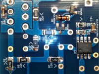
Post hi-res pics of your boards (top and bottom sides).
BTW... did you populate J1?
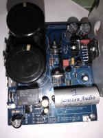
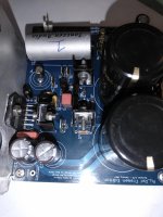
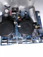
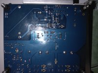
Here are my board pics
I can't see obvious faults.
Board seems somewhat dirty, with a lot of residues, did you clean it well?
Voltage readings
If you can explain the readings you have posted.
Help please!
I ve just built 1 board and have a bad result.
The first in one minute, i have a good result, the second measurement (+) values are ok, but (-). Then, everything messing up!.
DC offset: 16.8V
+ 32.8/35V
+ 1.25/1.25 V
+ 3.0/14.6 V
- 32.9V/-35V
- 0.51V/- 14.6 V
-1.25V/-1.25V
No Led, no click but when i switch off, led flash and click sound.
I changed another LM317 but received the same value.
Please help me what should i check now, step by step because i am newbie
Thank you
If you can explain the readings you have posted.
- Home
- Amplifiers
- Chip Amps
- My_Ref Fremen Edition - Build thread and tutorial