I have read a few papers from Bill Whitlock, and have learned a lot from them. But I do not recall any actually describing the change in perceived sound quality. I will check again.True enough - to get a handle on those I suggest looking out for a paper (which I've not read as its behind the AES paywall) of Deane Jensen - google for 'Spectral Contamination'. Bill Whitlock carries on the good work over at Jensen Transformers nowadays so he might be a good person to ask about audibility.
It very much depends on the whole system grounding - whether balanced or unbalanced cabling is used for example. The mechanisms for coupling are clear though - much depends on the resistance of amp to RF ingress. This I believe is the reason many audiophiles turn up their noses at IC opamps
I can tell you now that I am willing to stand a LM3886 chip amp up to any commercial amp for loads between 4ohm and 9ohm. Circuit is the standard NS data book, just special attention to power supply matching/decoupling.
Do you have insulation between the LM3886 abd heat sink? I sometimes forget them after a swap around.I forgot to mention. I took the FE's off my one large heat sink and attached them to separate computer heat sinks. Even though only one channel was working both heat sinks got warm. Would this suggest your first guess is correct; that I have a (almost) dead LM318 ?
DC Volt with the meter set on 200m V --- is 1.8 for the working side and 0.8 for the non-working side.
If that is what I did wrong, would the zener also be killed or could it be reused ?
I'm truly a novice here. Is this done on the pads with the LM318 removed or can it be done with the op-amp in place ? Which LM318 pins provide the supply voltage ?
BTW, I fixed the dead display segment on my meter and gave it a new battery; it is doing much better.
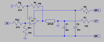
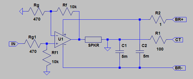
My take on the best possible decoupling scheme for a standalone LM3886 :I can tell you now that I am willing to stand a LM3886 chip amp up to any commercial amp for loads between 4ohm and 9ohm. Circuit is the standard NS data book, just special attention to power supply matching/decoupling.
Shown is the basic principle only (referring GND to a non-rippling neg supply to make use of the much better PSRR of the pos rail of the LM).
Will post full schematic and working amp with measurements some day (as I promised when I first posted this).
But we are polluting the FE thread here...
Attachments
Do you have insulation between the LM3886 abd heat sink? I sometimes forget them after a swap around.
No, just white heat sink paste but it is a LM3886TF.
I think the zeners at D105, D205 are in correct direction.
Attachments
Andrew, see this thread's section for some details. I'm still refining the circuit to make it bullet-proof for DIY. I might go back to the standard approach and make only the MF/HF decoupling this way, see also ThorstenL's comments.
No, just white heat sink paste but it is a LM3886TF.
It's perfectly fine, no need for insulation with TF.
I think the zeners at D105, D205 are in correct direction.
Yes, they are but I thnk Klaus was referring to D3 (27V one between BAV99s).
Can you post a clear picture of the bottom of the board?
How DO you guys get such clear pictures of small things ?
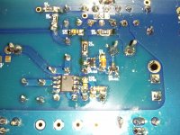
Here is a pic of the 27V SMD zener. The stripe is toward the 3886 on both boards. I have not tried to re-flow it yet.
I have on the way from Mouser: (1)LM3886TF, (2)LM318 smd, (4)BAV99 and some other things.
Here is a pic of the 27V SMD zener. The stripe is toward the 3886 on both boards. I have not tried to re-flow it yet.
I have on the way from Mouser: (1)LM3886TF, (2)LM318 smd, (4)BAV99 and some other things.
Attachments
How DO you guys get such clear pictures of small things ?
Firm hand, a lot of light and macro mode.
Here is a pic of the 27V SMD zener. The stripe is toward the 3886 on both boards. I have not tried to re-flow it yet.
It's correcty oriented.
But I see a lot of possible cold joints and solder bridges.
You probably use a too low temperature with you soldering iron, it should be at least 320°C.
Looking back on it, I'm sure on part of the build it was too cold. I have one of those Stahl variable temp w/ chisel tip from Parts Express. This build was the first time I used it. Now I see that 350C setting gives that 1 second melt we look for.
Thanks for the help guys. No more troubleshooting for me till Monday, work calls and I have new people on my crew.
Thanks for the help guys. No more troubleshooting for me till Monday, work calls and I have new people on my crew.
I have introduced concept in the original MyRef thread. The current configuration is working better than I expected. But the design is proprietary. Both the configuration and values effect sound quality.My take on the best possible decoupling scheme for a standalone LM3886 :
Shown is the basic principle only (referring GND to a non-rippling neg supply to make use of the much better PSRR of the pos rail of the LM).
Will post full schematic and working amp with measurements some day (as I promised when I first posted this).
But we are polluting the FE thread here...
http://www.diyaudio.com/forums/chip-amps/54571-my-audiophile-lm3886-approach-392.html#post3029324
http://www.diyaudio.com/forums/chip-amps/54571-my-audiophile-lm3886-approach-392.html#post3029094
C7 is actually 0.15uF when I looked the other day
The switching modules are off-the-shelf which I mentioned here
http://www.diyaudio.com/forums/chip-amps/196237-my_ref-revo-5.html#post2720051
This is enough for people to DIY. Nobody to date seemed interested though.
The line filter and additional matching with the circuit is proprietary.
Last edited:
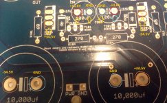
10000uf measures 33.7 and 33.8
100uf measures 14.3 and 14.4
IC101 measures 33.8
IC201 measures 33.8
They seem good measures, a bit on the low side but probably it's the transformer regulation.
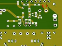
I have removed LM318 and LM3886. I've got a BIG problem. While removing LM318 a solder pad was torn away from the PCB.
Didn't used the Chip Quik desoldering alloy?
With it it's easy to desolder SMD chips without doing any damage...
Can you post a picture?
It should be possible to made a repair with a bit of copper wire or using a conductive silver pen.
Or, maybe, you're lucky and the lifted pad is one of the not connected ones.
Last edited:
My camera is picky right now. Looking at the underside of the board with the 3886 at the top, it is the bottom right pad .
This one?:
If so you're lucky... a not connected one
Attachments

- Status
- This old topic is closed. If you want to reopen this topic, contact a moderator using the "Report Post" button.
- Home
- Amplifiers
- Chip Amps
- My_Ref Fremen Edition - Beta build/Fine tuning