After giving some thought...
After giving some thought on what has been said here about power response, or the general more natural sounding off axis attenutation...well thats how i interpreted it, so i may have gotten the 'wrong end of the stick'.
With this in mind i modelled a few x-o mods and changed the baffle size and roundover, for the tweeter only and also offset the tweeter. This results in a ON axis response that is down around 1dB at 5kHz and 2dB at 10kHz and above. however i do think that this sim shows perhaps a better off axis behavior, and whilst not perfect, is WAY better.
first off the polars, theres 4 graphs here. If its too small ill repost again seperate. Each graph shows the direction away from we are moving away from 0 degrees. starting from top left we have:
left:links, right:rechts, over/up: oben, under/down: unten (Rudolf: correct me if im wrong!)
the 30 and o degree plots are every so slightly smoother, albeit with a declining HF of 2dBb over the range specified. so not amazing. the 60 line(the green one) is interesting. the bump at 60 before, which was after the saddle and around 5K if i remember right. now in the two bottom plots the rise is gone and the saddle seems to have gone too. what IS apparent though is a small rise at around 2k. IN the left and right plots(2 upper graphs), however, the 60 plot looks very nice. However, NOW the problem lies on the 90 degree plot, STILL at 5k. Since i am planning on using some felt on the baffle front around tweeter in a BBC monitor way, im hoping that this 1-2dB rise at 5k will be quelled a little. but despite the hiccup at 5k on the 90deg the power response looks better (i think).
Next the power response verses FR ON AXIS, which i gather is a summation of the polar effects.
And considering the old plots:
So....opinions? I think it looks a LOT better, but would be interested to know what others 'in the know' think.
Cheers.
Greg
After giving some thought on what has been said here about power response, or the general more natural sounding off axis attenutation...well thats how i interpreted it, so i may have gotten the 'wrong end of the stick'.
With this in mind i modelled a few x-o mods and changed the baffle size and roundover, for the tweeter only and also offset the tweeter. This results in a ON axis response that is down around 1dB at 5kHz and 2dB at 10kHz and above. however i do think that this sim shows perhaps a better off axis behavior, and whilst not perfect, is WAY better.
first off the polars, theres 4 graphs here. If its too small ill repost again seperate. Each graph shows the direction away from we are moving away from 0 degrees. starting from top left we have:
left:links, right:rechts, over/up: oben, under/down: unten (Rudolf: correct me if im wrong!)
An externally hosted image should be here but it was not working when we last tested it.
the 30 and o degree plots are every so slightly smoother, albeit with a declining HF of 2dBb over the range specified. so not amazing. the 60 line(the green one) is interesting. the bump at 60 before, which was after the saddle and around 5K if i remember right. now in the two bottom plots the rise is gone and the saddle seems to have gone too. what IS apparent though is a small rise at around 2k. IN the left and right plots(2 upper graphs), however, the 60 plot looks very nice. However, NOW the problem lies on the 90 degree plot, STILL at 5k. Since i am planning on using some felt on the baffle front around tweeter in a BBC monitor way, im hoping that this 1-2dB rise at 5k will be quelled a little. but despite the hiccup at 5k on the 90deg the power response looks better (i think).
Next the power response verses FR ON AXIS, which i gather is a summation of the polar effects.
An externally hosted image should be here but it was not working when we last tested it.
And considering the old plots:
An externally hosted image should be here but it was not working when we last tested it.
An externally hosted image should be here but it was not working when we last tested it.
So....opinions? I think it looks a LOT better, but would be interested to know what others 'in the know' think.
Cheers.
Greg
Last edited:
construction (or lack of) update
due to issues with the CNC man taking nearly 2 months to look over my panel cut outs, the lack of a quote for the work, and my desire to actually finish this project sometime before the nice weather tempts me outside; i have re thought out the construction of my TL, reverse taper horn...call it what you will
so..... contrary to my initial design:
i am now pursuing the option of making said tapered TL in a translam construction method, in either MDF or decent ply. Despite reservations against MDF, (and all the opinions of others), I will probably go the MDF road, since obtaining good ply is beginning to frustrate me
intitially i WAS going to cut the lams with an angle to match the taper ratio of the TL and create smooth internal face, however after much thought, reading about the BVRs and others here on the forum, as well as the desire to make construction as painless as possible, i have come to a conclusion.
Sod making the angles and just leave the taper stepped, all the while hoping that the stepping should provide some LP filtering in a similar way as in some of scotts BVR and other double horn designs.
That decision sorted, for the moment, I can eventually start with the construction!!!
due to issues with the CNC man taking nearly 2 months to look over my panel cut outs, the lack of a quote for the work, and my desire to actually finish this project sometime before the nice weather tempts me outside; i have re thought out the construction of my TL, reverse taper horn...call it what you will
so..... contrary to my initial design:
An externally hosted image should be here but it was not working when we last tested it.
i am now pursuing the option of making said tapered TL in a translam construction method, in either MDF or decent ply. Despite reservations against MDF, (and all the opinions of others), I will probably go the MDF road, since obtaining good ply is beginning to frustrate me
intitially i WAS going to cut the lams with an angle to match the taper ratio of the TL and create smooth internal face, however after much thought, reading about the BVRs and others here on the forum, as well as the desire to make construction as painless as possible, i have come to a conclusion.
Sod making the angles and just leave the taper stepped, all the while hoping that the stepping should provide some LP filtering in a similar way as in some of scotts BVR and other double horn designs.
That decision sorted, for the moment, I can eventually start with the construction!!!
I dont seem to get anything done quickly do i?
following the cnc crisis, i have started building of the lammed version of my qwt design:
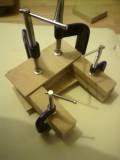
the 'stepped' lams im using to build my speakers. each one is 25mm thick, with the depth of the section diminishing 6mm with each new section. this is the bottom-most sections of the box. there will be a large amount of solid MDF at the bottom of the box and this is advantageous to stability. This should also be conducive to providing inertial resistance to low frequency movement, coupled with spikes should provide good LF 'tightness'. ply would be used if i could get some decent enough and didnt think it was wasted in this app.
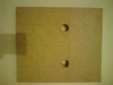
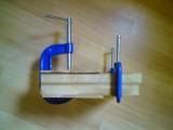
these 2 pic show the lams im using to house the crossover in. there will be 5 lams like this in total yielding a space of about 5"x5"x5" fot the crossover components to sit in. when nearly all lams are assembled, all but the last 10 or so, the sides, baffle and rear panel will be glued to the respective edges. this is provided of course that the edges are level enough. if not the belt sander may have to come out of retirement! the last few sections will be glued directly to the other lams AND the rear panel , since they would be too thin to do otherwise.
the exterior cladding may be good ply, if i can get some, or failing that MDF or butcher block counter top,although the latter is a tad expensive....
following the cnc crisis, i have started building of the lammed version of my qwt design:
the 'stepped' lams im using to build my speakers. each one is 25mm thick, with the depth of the section diminishing 6mm with each new section. this is the bottom-most sections of the box. there will be a large amount of solid MDF at the bottom of the box and this is advantageous to stability. This should also be conducive to providing inertial resistance to low frequency movement, coupled with spikes should provide good LF 'tightness'. ply would be used if i could get some decent enough and didnt think it was wasted in this app.
these 2 pic show the lams im using to house the crossover in. there will be 5 lams like this in total yielding a space of about 5"x5"x5" fot the crossover components to sit in. when nearly all lams are assembled, all but the last 10 or so, the sides, baffle and rear panel will be glued to the respective edges. this is provided of course that the edges are level enough. if not the belt sander may have to come out of retirement! the last few sections will be glued directly to the other lams AND the rear panel , since they would be too thin to do otherwise.
the exterior cladding may be good ply, if i can get some, or failing that MDF or butcher block counter top,although the latter is a tad expensive....
Last edited:
- Status
- This old topic is closed. If you want to reopen this topic, contact a moderator using the "Report Post" button.