Hi Jaka,
please take a look into their datasheets. As I believe (if the datasheets are reliable), the ISL parts seem to be faster: typical Tp is 20ns vs. 24/25ns, the Bootstrap diodes Tbs is 10ns vs. 50ns (!), the maximum output current is higher, clearly to bee seen in the diagrams of the peak output currents vs. output voltages.
But National seems to be a bit cheaper... In contrast to that the HIP is available at Farnell in small quantities.
Unfortunately I'm not able to bring "my" design into working in the near future. I'm a "bit late" with my Uni-project. As every time I underestimated the development effort.
At home we had to refurbish. And so on...
The time will come! I am still hopeful.
And I am still grateful for your and the other's experts help.
Best regards, Timo
some follow-ups
I finally had some time to get my amp out of the subwoofer again, and do some measurements.
I checked the triangle generator. It runs at 260kHz, so obviously the formula on that webpage seems to be wrong.
I also measured the output with a 4 Ohm woofer connected. First of all, the frequency response is much better than expected!! It easily goes up to 30kHz. It is linear from 5Hz to 22kHz, then it goes up a bit (about 10%) at 27kHz (I guess that is the resonance of the output filter). Above that, it drops off. I have no idea why I got different measures before, when I measured it at 8 Ohm resistors.
I also have to admit that it is not entirely load-independent. When I measured with the speaker connected, but the enclosure openened (bascally the speaker could move freely), then it was linear. But as I closed the sealed enclosure, the AC voltage at the speaker terminals went up a bit around 120Hz. I don't know the resonance frequency of the enclosure, but it must be much lower, around 60 or 70 Hz. It's a 60l sealed box, with a 12" woofer.
Does anyone have an explanation for this? My theory is, that the speaker works "against" the resonance at this frequency, such that it has a higher impedance. I remember that BCA stands for "Balanced Current Amplifier". So maybe the current remains linear, while the voltage may vary with the impedance.
And, though the voltage at the terminals changed during sine sweeps, the observed loudness of the speaker remained fairly constant (I didn't have my microphone with me, so I could only listen, but I couldn't hear any changes in loudness during the sweeps)
So, is this good or bad? Where are the experts? Obviously, on a resonant load like a speaker, with varying impedance, it is impossible to keep voltage AND current both linear. What is more desirable, linear voltage, or linear current (over different frequencies, of course)? Theoretically, linear in Power would be best, I think, but still, in combination with a speaker, which has different efficiency around resonance, it may not be the best solution.
Any ideas?
Cheers,
Felix
2 questions:I have been playing around with this Excel calculator,
and I´ve noticed that if I use a lower switching frekvency I get higher poweroutput,how is that so? And is it possible to use your
design with say 100Khz?
If I use this design with this Switchmode power supply: http://sound.westhost.com/project89.htm
and only use the possitive output +35v.Or must I use both + and - at the same time?I´ts for my holliday house where I only have 12 volts.
Attachments
Commentable Thoughts
I think TEXAS INSTRUMENT is using BCA TOPOLOGY in their Class-D amps ICs.Check The Datasheet of TPA3001D1 Class-D IC.
Did they got the license or just voilating the Crown's Patent.
http://www-s.ti.com/sc/ds/tpa3001d1.pdf
Compliments
Ampman
I think TEXAS INSTRUMENT is using BCA TOPOLOGY in their Class-D amps ICs.Check The Datasheet of TPA3001D1 Class-D IC.
Did they got the license or just voilating the Crown's Patent.
http://www-s.ti.com/sc/ds/tpa3001d1.pdf
Compliments
Ampman
Attachments
Commentable Thoughts
Ampman ThanX JAKA RACMAN for Clarifying Misconception regarding BCA.
Would u plz do me a favour about that How BD[Balanced Drive maybe or not] modulation works?
With Compliments
Ampman
Jaka Racman said:Hi,
BCA and BD modulation are not the same. Do some more research.[
Best regards,
Jaka Racman
Ampman ThanX JAKA RACMAN for Clarifying Misconception regarding BCA.
Would u plz do me a favour about that How BD[Balanced Drive maybe or not] modulation works?
With Compliments
Ampman
Commentable Thoughts
The Above Quote BCA modulation is very similar to BD modulation as described by JAKA RACMAN and which is used by TEXAS INSTRUMENTS.
I am Confused Guys!
PLZ Help me.
Whats the difference between BCA & BD modulation can anyone explain?
CONFUSED COMPLIMENTS
AmPmAn
sfx said:Hi Timo,
For the whole audio band, 250 kHz is enough. The professional Crown amps also have only 250kHz. If you have a close look at the BCA principle, you will realise, that the effective frequency is 500kHz.
Nominally, both PWMs are on at the same time, at 50% duty cycle, so they cancel each other out.
The output voltage is proportional to the difference in duty cycle between the two in-phase PWM signals. So you'll get a short pulse at the beginning, then both are on, so the result is 0, then again a short pulse. The base frequency doubles, but all active parts run at base frequency.
1.) no signal
____----____----____----____
____----____----____----____
output:
____________________________
2) positive signal
___------___------___------___
_____--_______--_______--_____
output:
___--__--___--__--___--__--___
Cheers,
Felix
The Above Quote BCA modulation is very similar to BD modulation as described by JAKA RACMAN and which is used by TEXAS INSTRUMENTS.
I am Confused Guys!
PLZ Help me.
Whats the difference between BCA & BD modulation can anyone explain?
CONFUSED COMPLIMENTS
AmPmAn
Commentable Thoughts
IN BCA the output stage employs inductors and free wheeling diodes, can assume same in case of BD modulation?
My question is If we eliminate inductors and Diodes in BCA modulation , then it becomes BD modulation??
AAAAMMMMPPPPMMMMAAAANNNN
Can we say BCA is Modified version of BD modulation.Jaka Racman said:BCA is special type of output stage which also uses BD type modulation.
Best regards,
Jaka Racman
IN BCA the output stage employs inductors and free wheeling diodes, can assume same in case of BD modulation?
My question is If we eliminate inductors and Diodes in BCA modulation , then it becomes BD modulation??
AAAAMMMMPPPPMMMMAAAANNNN
I don't know about BD modulation, but if you eliminate the inductors in a BCA topology, then you'll get burning MOSFETs, because they are both on at the same time. If you remove the diodes, then most likely inductive voltage spikes from the filter or the speaker will destroy your FETs as well.
Can anyone enlighten us how BD without BCA looks like? Is it patent-free?
Felix
Can anyone enlighten us how BD without BCA looks like? Is it patent-free?
Felix
Hi,
it is very simple. If you take classic full bridge output stage and designate sides as R and L and their states as H and L, then in class AD modulation you have only two states: LH,RL and LL, RH. In class BD you have aditional third state LL,RL or LH,RH. Both third states are equivalent. Class AD and BD are analogic to linear class A and B in that you have AC current flow through output stage with zero signal input in class AD and in class BD, there is zero current flow ( load is effectively shorted by alternating only between both third states) when idling. I am not sure if the principle of class BD modulation is patented, but specific implementations are (like using filterless output stage or ripple cancelation with double bridge output stage).
Best regards,
Jaka Racman
ok,...
but how do you avoid shoot through and destruction of the MOSFETs, which have, being switching devices, a very low resistance, in contrast to biased class A or B amplifiers?
BCA avoids this problem by inserting inductors, so that the energy can be stored and flow back during the off cycles. I can't really see how you can have BD without BCA.
I also found out that Rockford Fosgate has a patent on BD, but couldn't find any technical details.
Hi,
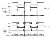
seems I was not clear enough. LH state means that upper transistor in left leg of full bridge is conducting and lower transistor is not. LL means the opposite, lower transistor is conducting and upper not. So there are no shoot through currents.
Better still, here is the TPA3001 data sheet. Read page 15.
Best regards,
Jaka Racman
Hi,
alright, now I got it. It only applies to full bridge. This idea is not bad either! The main difference to BCA is that BCA can be operated as non-bridged, with the speaker between output and GND. As I understand, they both share the frequency-doubling behaviour and the smoother zero-crossing with ripple rejection.
The modulation is very different, though. In BD, upper and lower MOSFET are switched strictly alternating, and the two half-bridges operate in phase. In BCA, upper and lower MOSFET are in phase.
The BD amplifier still has a dead-time at zero-crossing. By shifting the phases of the two half-bridges, this can be eliminated, as shown in the datasheet, but this produces some ripple at zero input. BCA has zero ripple at zero input, and ripple increases proportionally with the amplitude.
On the other hand, I can imagine that BD could have lower output impedance, since it doesn't rely on filters to function, so they can be smaller. BCA needs inductors to work.
It's funny, I also had an idea how to solve the deadtime/shootthrough problem, but noone seems to use it yet.... maybe I should file a patent, it seems to be quite easy...")
alright, now I got it. It only applies to full bridge. This idea is not bad either! The main difference to BCA is that BCA can be operated as non-bridged, with the speaker between output and GND. As I understand, they both share the frequency-doubling behaviour and the smoother zero-crossing with ripple rejection.
The modulation is very different, though. In BD, upper and lower MOSFET are switched strictly alternating, and the two half-bridges operate in phase. In BCA, upper and lower MOSFET are in phase.
The BD amplifier still has a dead-time at zero-crossing. By shifting the phases of the two half-bridges, this can be eliminated, as shown in the datasheet, but this produces some ripple at zero input. BCA has zero ripple at zero input, and ripple increases proportionally with the amplitude.
On the other hand, I can imagine that BD could have lower output impedance, since it doesn't rely on filters to function, so they can be smaller. BCA needs inductors to work.
It's funny, I also had an idea how to solve the deadtime/shootthrough problem, but noone seems to use it yet.... maybe I should file a patent, it seems to be quite easy...
Hi,
BD modulation does not apply only to full bridge. Take BCA output stage, replace diodes with transistors and you have ground referenced BD amplifier. You can get rid of output inductors by using smal center tapped autotransformer. Very clever idea, but not mine and it is also patented.
Best regards,
Jaka Racman
Commentable Thoughts
Hi Guys ,
I have interacted with TI about the Patent on Class-BD, They insure it is not Patented.
While on otherhand Rockford Frostgate have patented a slightly different variant of Class-BD modulation.
Several Companies Such as ECLER , Apogee, Reinbeck are using Class-BD modulation.
Now I will Also Turn my hands on BD modulation.
Compliments
Ampman
Commentable Thoughts
Can u plz tell me?
IF I insert a deadtime delay using Resistor+Capacitor+diode combination at the hi-lo inputs of IR2110 driver,do they require optional CMOS Buffer at input stage or not.
Acc to my knowledge IR2110 has inbuilt input buffers.
Compliments
Ampman
Can u plz tell me?
IF I insert a deadtime delay using Resistor+Capacitor+diode combination at the hi-lo inputs of IR2110 driver,do they require optional CMOS Buffer at input stage or not.
Acc to my knowledge IR2110 has inbuilt input buffers.
Compliments
Ampman
- Status
- This old topic is closed. If you want to reopen this topic, contact a moderator using the "Report Post" button.
- Home
- Amplifiers
- Class D
- My very first Class D pwm (switching) amplifier.