Re: continuous and discrete
Maybe I did not express myself well... When I said continuous-time, I mean that the pulse width can take any value (it does not have to fall on clock edges). With this definition, 1-bit DACs are time-quantized, Class D amps like Tripath are time-quantized, self-oscillating Class D amps are time-continuous, and PWM with comparison to a triangle signal is time-continuous (because the triangle signal is continuous).
It could be argued that PWM using a triangle signal has some time-quantization in it, as it kind of "samples" the input signal at the instant of comparison with the triangle wave. This is not what I was talking about, but it also causes problems, as the sampling instant varies with signal intensity (as it crawls along the triangle) , which is simply Jitter.
Now, I very much agree that "These criteria alone don't determine the sound quality of a final amp. As always it is not only a question of what principle you use, it is a question of how you implement which principle.", especially on switching and HF things.
I'm very interested in ClassD amps and would like to build one. However I can't design an output stage because I have no background in switching supplies. I would like to try, though.
"P.S.: D-S amps use overall feedback so they cannot exactly be compared to 1-bit DACs"
But 1-bit DACs are practically all delta-sigma designs so we end up where we started... except some parts are implemented in analog domain in D-S amps whereas everything is digital in 1-bit DACs.
What I want to say is that quantizing pulse lengths is an unnecessary hurdle. 1-bit DACs suck, every chip manufacturer has moved away from them, this should be considered as known fact now. Why replicate this in ClassD amps ? In my opinion, designs with continuously variable pulse width have more potential.
Cheers
I think the CREST design relys just on PSU capacitance and LF cutoff regarding the PSU pumping problem.
Supply pumping is a function of output stage modulation, load current and signal frequency.
The worst situation is delivering a high DC current at a very low output voltage, i.e. into a very low load impedance.
The voltage buildup can not only destroy the FETs it can also get dangerous for the PSU caps (once done personally at the lab).
I've heard some P.A. people saying that the bass quality of switching amps was inferior to that of conventional amps.
My opinion is the contrary. Maybe the amps they listened to didn't have enough generously designed PSUs. Or maybe they had just bad taste regarding sound quality and the amps simply didn't sound bad enough !!
I suspect that some designers think that you can build a switching amp the real cheap way and try to save too much money on PSU and heat-sinking.
Regards
Charles
I think that the sound performance of class D could be superior since it can supply more power to the load in a shorter time. Other types have to be held back for stability.
Hi IVX,
I am still working on the PS pumping problem. I have to correct the earlier idea that it is caused by the speaker inductance. It may be caused more by the output filter inductance.
I haven't looked into searching for a dual NPN transistor yet. I am not sure how much DC offset temperture drift would cause. Best Regards.
Don't forget that it is quite unimportant to a switching amp, into what kind of load it delivers it's power. This statement is only valid for signal frequencies well below the output filter's cutoff frequency.
Average class AB amps usually employ some sort of SOA protection that spoils their ability to drive complex loads with ease.
Regards
Charles
Average class AB amps usually employ some sort of SOA protection that spoils their ability to drive complex loads with ease.
Regards
Charles
Hi all,
subwo, don't worry, to avoid pumping effect problems (for half bridge) just use: A) cap's & mosfet's at biger voltage B) subsonic input filter, oh yea- DC really dangerous (be cause DC offset important too). C) single regulated PS (one for + & one for - 80v) or no regulated even.
subwo, don't worry, to avoid pumping effect problems (for half bridge) just use: A) cap's & mosfet's at biger voltage B) subsonic input filter, oh yea- DC really dangerous (be cause DC offset important too). C) single regulated PS (one for + & one for - 80v) or no regulated even.
There are several ways of dealing with the supply pumping effect:
1.) Generously dimensioned PSU caps (never a bad idea anyway).
2.) Avoiding DC at the output
3.) Amps either built as full bridge or stereo amps with one channel inverted
4.) A circuit like the one patented by Tripath. It does basically transform the excess voltage on one rail to the other one. IMO this one is too complicated.
5.) A capacitive charge-pump circuit that equals out the voltage of the two rails. Basically four MOSFETs that alternately switch a capacitor between both rails at high speed (ideally synchronised to the amp's switching frequency).
6.) For conventional PSUs only: A clamping circuit that connects the PSU cap to the transformer's secondary during the peak voltage period as soon as the cap's voltage exceeds the peak secondary voltage. This would have to be done with great precision in order to avoid unintentional fireworks.
Regards
Charles
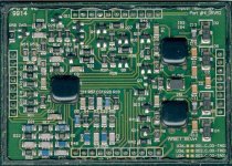
Really beautiful! by the way... what's that?
Looks like one of the Tripath modules that has been cut open.
Regards
Charles
And again a riddle
An externally hosted image should be here but it was not working when we last tested it.
ssanmor said:Really beautiful! by the way... what's that?")
Tripath TA0104A without cover
I think that these two black drops on right side is IR2110/3
Now that my amp is working well and I am more familiar with Class-D design, I will try to simplify it as much as possible.
I think it worths the pain to test the MAX4295 chip, so I will re-design the modulator and level-shifting part of my amp.
I think that the XOR gates can be eliminated, then using both outputs of the MAX4295 and level shift-them with the same method. Both shifted signals are then passed to the R-C-D circuit that has worked well in my previous design and then to the IR2110. The rest reamins exactly the same as before.
Now that I am going to re-design the board, I will try to make it single-sided to simplify its etching and mounting.
I will tell you how it goes.
A stupid question:
The MAX4295 has single supply, with the + input connected to a stable reference = 0.3xVcc (1.5V in my case).
The input must be decoupled by a capacitor in series with the input resistor, so the cutoff frequency is low enough (10Hz or so).
But how do I connect the feedback signal? I plan to avoid the use of other input opamps in order to increase simplicity, so I want the input opamp of the MAX4295 to be the error amplifier. The feedback signal has no theorethical DC offset, so how can I couple it to the input opamp of the MAX4295?
Thanks
- Status
- This old topic is closed. If you want to reopen this topic, contact a moderator using the "Report Post" button.
- Home
- Amplifiers
- Class D
- My very first Class D pwm (switching) amplifier.