Hi,
I have these fluctuations, too, in a high gain, 8 parallelled JFET phono amplifier, but got less by potting all the JFETs and source resistors and using a large heat sink (10mA Id each).
I am curious, is parallelling the cause of these fluctuations thinking that the exact current sharing is changing over time?
Gerhard,
Some conclusions:
- Low noise fluctuations of allegedly thermal origin decreased significantly when lowering the Id (and hence the power dissipation). Scott could be right, these fluctuations could be due the convection at board level, although a previous model running at Idss and enclosed in 1/2" of metal has the same fluctuations amplitude and frequency (on average, once every 3-4 seconds) as in free air. Interesting enough, the fluctuation frequency for the low power case remained the same, only the amplitude decreased significantly. I am still puzzled by these fluctuations, which, BTW, are specific to the sigle ended topology. Never seen such in any op amp or discrete differential implementation.
P.S. The input cap is a rather new 1uF 1206 film device http://www.cde.com/resources/catalogs/FCA.pdf To my surprise, it is of excellent quality, zero microphonics and very low leakage. DigiKey has them in stock.
I have these fluctuations, too, in a high gain, 8 parallelled JFET phono amplifier,
Thank you, for some reason I hadn't noticed posts on LF noise. Can you share any measurement data?
I am curious, is parallelling the cause of these fluctuations thinking that the exact current sharing is changing over time?
I don't know, but I certainly doubt it has anything to do with current sharing in the JFETs. Though it is, most likely, some sort of thermal effect.
In aplication note 159;
https://www.analog.com/media/en/technical-documentation/application-notes/an159fa.pdf
They made 2 different version of amplifier single ended input (page 4) and differential input (page 14), I do not understand how they connect single ended output LT3045 (dut) device to differential input amplifier on page 15. Could you please explain ?
LT3045 GND to Amplifier IN(-) ?
Last edited:
Sorry, but this was a few years ago, and I could not find the measurements.
Thank you, for some reason I hadn't noticed posts on LF noise. Can you share any measurement data?
Yes, most likely a thermal effect which is not easy to mitigate.
For the 8 JFETs each running at 1mA, how are the source currents split with just one ccommon source resistor?
For the 8 JFETs each running at 1mA, how are the source currents split with just one ccommon source resistor?
I don't know, but I certainly doubt it has anything to do with current sharing in the JFETs. Though it is, most likely, some sort of thermal effect.
Attachments
I imagine the FETs have to be matched/sorted so that gate voltages are similar at Id of 1mA; individual in circuit Id will of course vary since there's no inherent regulation of the individual channel currents.
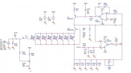
I think the circuit is very clever--- my complements to the designer. I do see one minor concerning issue in the schematic posted in #570: I believe the U1B stage is susceptible to local oscillation because R453/R418 and the opamp input capacitance will present a low frequency pole (~4 kHz) and very poor damping of this stage. I believe 10pF shunting R453 would be an easy remedy.
I think the circuit is very clever--- my complements to the designer. I do see one minor concerning issue in the schematic posted in #570: I believe the U1B stage is susceptible to local oscillation because R453/R418 and the opamp input capacitance will present a low frequency pole (~4 kHz) and very poor damping of this stage. I believe 10pF shunting R453 would be an easy remedy.
At low frequencies, R418 and C201 (and of course the opamp) form the integrator you alluded to earlier; integrator gain drops with increasing frequency until C201 reactance equals R543's 10M; at this "corner frequency" (~0.032Hz), the opamp gain becomes flat with increasing frequency.
At this same corner frequency, low-pass filter R416 and C202 begin to attenuate increasing frequencies. The net result is that between R418 input and Q7 base, the gain drops smoothly at 6dB/octave--- an integrator! Said in fancy talk, the C201/R543 "zero" cancels the C202/R416 "pole."
At this same corner frequency, low-pass filter R416 and C202 begin to attenuate increasing frequencies. The net result is that between R418 input and Q7 base, the gain drops smoothly at 6dB/octave--- an integrator! Said in fancy talk, the C201/R543 "zero" cancels the C202/R416 "pole."
Yes, most likely a thermal effect which is not easy to mitigate.
For the 8 JFETs each running at 1mA, how are the source currents split with just one ccommon source resistor?
No need to do anything special, one common source resistor is good enough, JFETs are not hogging current like bipolars and vertical MOSFETs do.
Any JFET circuit can be designed for an exact zero temperature coefficient https://www.interfet.com/jfet-datasheets/jfet-an-107-interfet.r00.pdf but even if not, it's usually close enough to zero tempco to avoid any current hogging and thermal runaway.
Hmmm. I don't see it ...
Without R453 the response will badly overshoot at low frequencies, it can even motorboat. R453 creates a zero in the servo loop gain (at low frequency) which exactly compensates/cancels the extra pole.
A more interesting question is why is the extra pole at the servo output required? Since a resistor at the servo output is needed (to provide the current source base current), and the opamp has it's own noise, the combined noise would be injected in the current source and amplified at the second gain stage input. C202 makes sure this noise source is bypassed.
For those concerned about the pole resulting by 10Meg and the U1B input capacitance, a back of envelope calculation (or Spice simulation) shows it is of no concern. Assume 10pF with 10Meg renders a pole (zero in the servo feedback loop) at 1.6KHz. That's way over the LP servo bandwidth (between 1-2Hz), at 1.6KHz the servo loop gain is already 0dB, so the effect of this pole can safely be ignored. Experimentally, there's no observed effect.
Last edited:
I think the circuit is very clever--- my complements to the designer.
Thank you
 . BTW, by simply translating the voltages, the amp could be made to work from a single supply, I can see it working (with extra care in biasing) even from a single 9V cell using 10-12mA. An output cap would be required, of course.
Last edited:
- Home
- Design & Build
- Equipment & Tools
- My version of the G = 1000 low noise measurement amp (for Ikoflexer)