I wanted to share with you all my (mostly) completed pre-amp. I hope this is allowed and adds a unique implementation of the PGA2310 volume control to the forum. This project was inspired by Mark Hennessy’s great design (details here: https://www.markhennessy.co.uk/preamp/). I modified the design to better suit my much less ambitious needs. I also made a full embrace of surface mount technology and leveraged more advanced chips where convenient. This project started literally about 10 years ago (my last post was asking for some explanation of Mark's design) and I got it to 95% complete last year. Image are below. I have a video, but seems I can't upload it.
Volume Control
Like Mark, I based my design on the TI PGA2310 digital volume control with input and output buffers based on the OPA2134 and NE5332. The PGA2310 is the only IC in my design that utilizes a DIP package and that's because I was able to get free samples from TI and the DIP was somewhat better for my layout. On the buffers, I used SMD resistors and capacitors with impunity (except for the large coupling caps on the output). The SMD capacitors were all PPS capacitors as a very smart designer told me that these are appropriate for signal pathways. These are pretty fragile to solder manually, but I used reflow techniques and it was totally fine.
Source Selection
I didn't have crazy needs, just wanted to switch between my iPod, laptop, and desktop. I was originally planning on making one input a USB input for the iPod and using the MCU to do play/pause/etc. But, as the development phase outlived the iPod, that feature quickly got axed. In the end, I settled on two unbalanced RCA inputs and one balanced mini-XLR input (using the INA1650 as a balanced line receiver). The much reduced source number was also driven by a desire for a smaller PCB and a desire to have fewer than 7 push buttons (for programming reasons). On the output side, there is a line out and a variable out.
The sources are selected using Panasonic TQ2 SMD relays. These are small, SMD, and designed for telecom, so I hoped they would be okay for audio. I can't tell the difference! There's 3 for each input and 1 for the variable out.
If the SSM2404 were still around, you can bet I would have used those.
Power
Unlike Mark, I fully embraced modern voltage regulators and again, chased after those SMD packages. The digital side is powered at 5V by an ADM7150 LDO. The analog side is powered by the TPS7A39 bipolar LDO at +/-15V. The TPS7A39 was quite annoying to solder. I was lazy about fixing the footprint to ensure that it was in compliance with the board house design rules and had a shorting issue on an early design. This IC is also the one component that necessitated reflow (though I prefer reflow anyway as the board isn't full of flux residue after I'm done populating) because it has an exposed pad. During the pandemic, this IC was also hit hard by the supply chain issues. My suspicion was that it was initially designed for automotive applications and those suppliers were snatching up all the supply. I'm currently using a part that was salvaged from an earlier prototype. That's how desperate I was to get the part (I asked around a lot... even asked friends in China to help me find some off Alibaba). However, I couldn't find any alternate bipolar regulator that was this small and fit my needs, so I stuck with it.
In Mark's design, he had a separate supply just for the relays. I couldn't fathom a non-paranoid reason for that, so I just went with the 5V version of the TQ2 relays and powered them off the digital.
I also had another small LT1761 LDO at 5V to power my relay delay (more on that below). I could have used the digital 5V, but it would have led to a lot of segmentation of my power plane, so I decided against it.
In terms of grounding, I originally tried to follow the PGA2310 data sheet and have separate analog and digital grounds, but that became really annoying because I had to route a 5V return in the analog region for the un-mute relay. In the end, I decided just having a large continuous ground plane was good enough for me, no need to get hyper paranoid.
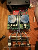
I also built un-regulated power supplies using Talema PCB mount toroidal transformers (these were Amveco when I started my project) to rectify and step-down the wall AC.
Relay delay/power supervisor
Mark uses a really complicated turn-on delay and voltage drop detection circuit based upon FETs and caps. I thought I figured it out enough to implement it in my different setting, but just couldn't get it working reliably. I ended up using a TPS3839 to monitor the input voltage to the LT1761. It also has a 200ms delayed turn on for the monitored voltage. When this voltage drops, it will open a TPS22860 switch that powers the un-mute relay. So, when the power droops, the output should be muted, protecting downstream components. I've not tested this, but hopefully it works. Get real. I'm lucky enough to live in an area with reliable enough power.
MCU
I settled on the PIC16F886. I didn't need all of the extra pins on the PIC16F887 that Mark uses in his design. I used a similar trick for the button detection where I used the ADC and a voltage ladder. I was all about hyper efficiency, so I designed the ladder to use the 3 MSB and those are added to the PCL to determine a destination. That was another reason I ended up with only 3 inputs (because I was also planning an un-mute, play-pause, and perhaps another button).
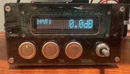
The "interface" is driven solely by an optical rotary with integrated pushbutton and the three source selection buttons. Currently, I only have source selection and volume control programmed. The push button is used to toggle the display on or off since it's so bright and I don't want burn in.
The SPI peripheral on the MCU is used to control the source selection relays, the input button indicator lights, and program the VFD. I had planned to use the UART peripheral to control the iPod, but we all know how relevant that is these days.
The firmware is in PIC assembly like on Mark's design. I had to download an old version of MPLAB to get the MPASM compiler. It was a fun learning experience.
Display
For the display, I chose the Noritake-Itron GU140x16G-7003B. I don't even know if this model has been officially released since. When I bought the VFD, the SPI version had been announced but not formally released. I emailed Noritake and inquired about it and was able to execute a transaction over email. I'm glad I was finally able to use that display because when I bought it, I was a poor student and it was an expensive purchase.
Layout
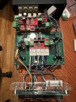
As you'll see from the images, I kept most of the design on a single PCB. There are separate PCBs for each of the unregulated power supplies and a glorified breakout board for the front panel. Other than the front panel PCB, they're all four layer boards.
Enclosure
I designed an enclosure around the extruded aluminum case used by the Mercury Helios 3S. I found a pair of discarded enclosures in the trash and knew these would be perfect. Currently, the case design makes liberal use of acrylic since that was cheap and easy to cut on a laser cutter. Eventually I would like to make some proper front and back panels using aluminum, but I'm too cheap and not motivated enough right now. It'd also be nice to have an actual window over the VFD.
Testing
No, I haven't bothered doing quantitative testing. I'm too lazy to make an adapter for BNC to RCA and find a function generator and spectrum analyzer or scope. And then if I wanted to test cross talk I'd need a second function generator? And if I wanted to check phase offsets between the L/R channel I'd need a network analyzer? No thanks. It sounds fine on my speakers. Good enough for me.
Next steps
Final words
Happy to answer questions if you have them. Hope my project can inspire all of you who have dormant projects to finally finish them.
Volume Control
Like Mark, I based my design on the TI PGA2310 digital volume control with input and output buffers based on the OPA2134 and NE5332. The PGA2310 is the only IC in my design that utilizes a DIP package and that's because I was able to get free samples from TI and the DIP was somewhat better for my layout. On the buffers, I used SMD resistors and capacitors with impunity (except for the large coupling caps on the output). The SMD capacitors were all PPS capacitors as a very smart designer told me that these are appropriate for signal pathways. These are pretty fragile to solder manually, but I used reflow techniques and it was totally fine.
Source Selection
I didn't have crazy needs, just wanted to switch between my iPod, laptop, and desktop. I was originally planning on making one input a USB input for the iPod and using the MCU to do play/pause/etc. But, as the development phase outlived the iPod, that feature quickly got axed. In the end, I settled on two unbalanced RCA inputs and one balanced mini-XLR input (using the INA1650 as a balanced line receiver). The much reduced source number was also driven by a desire for a smaller PCB and a desire to have fewer than 7 push buttons (for programming reasons). On the output side, there is a line out and a variable out.
The sources are selected using Panasonic TQ2 SMD relays. These are small, SMD, and designed for telecom, so I hoped they would be okay for audio. I can't tell the difference! There's 3 for each input and 1 for the variable out.
If the SSM2404 were still around, you can bet I would have used those.
Power
Unlike Mark, I fully embraced modern voltage regulators and again, chased after those SMD packages. The digital side is powered at 5V by an ADM7150 LDO. The analog side is powered by the TPS7A39 bipolar LDO at +/-15V. The TPS7A39 was quite annoying to solder. I was lazy about fixing the footprint to ensure that it was in compliance with the board house design rules and had a shorting issue on an early design. This IC is also the one component that necessitated reflow (though I prefer reflow anyway as the board isn't full of flux residue after I'm done populating) because it has an exposed pad. During the pandemic, this IC was also hit hard by the supply chain issues. My suspicion was that it was initially designed for automotive applications and those suppliers were snatching up all the supply. I'm currently using a part that was salvaged from an earlier prototype. That's how desperate I was to get the part (I asked around a lot... even asked friends in China to help me find some off Alibaba). However, I couldn't find any alternate bipolar regulator that was this small and fit my needs, so I stuck with it.
In Mark's design, he had a separate supply just for the relays. I couldn't fathom a non-paranoid reason for that, so I just went with the 5V version of the TQ2 relays and powered them off the digital.
I also had another small LT1761 LDO at 5V to power my relay delay (more on that below). I could have used the digital 5V, but it would have led to a lot of segmentation of my power plane, so I decided against it.
In terms of grounding, I originally tried to follow the PGA2310 data sheet and have separate analog and digital grounds, but that became really annoying because I had to route a 5V return in the analog region for the un-mute relay. In the end, I decided just having a large continuous ground plane was good enough for me, no need to get hyper paranoid.
I also built un-regulated power supplies using Talema PCB mount toroidal transformers (these were Amveco when I started my project) to rectify and step-down the wall AC.
Relay delay/power supervisor
Mark uses a really complicated turn-on delay and voltage drop detection circuit based upon FETs and caps. I thought I figured it out enough to implement it in my different setting, but just couldn't get it working reliably. I ended up using a TPS3839 to monitor the input voltage to the LT1761. It also has a 200ms delayed turn on for the monitored voltage. When this voltage drops, it will open a TPS22860 switch that powers the un-mute relay. So, when the power droops, the output should be muted, protecting downstream components. I've not tested this, but hopefully it works. Get real. I'm lucky enough to live in an area with reliable enough power.
MCU
I settled on the PIC16F886. I didn't need all of the extra pins on the PIC16F887 that Mark uses in his design. I used a similar trick for the button detection where I used the ADC and a voltage ladder. I was all about hyper efficiency, so I designed the ladder to use the 3 MSB and those are added to the PCL to determine a destination. That was another reason I ended up with only 3 inputs (because I was also planning an un-mute, play-pause, and perhaps another button).
The "interface" is driven solely by an optical rotary with integrated pushbutton and the three source selection buttons. Currently, I only have source selection and volume control programmed. The push button is used to toggle the display on or off since it's so bright and I don't want burn in.
The SPI peripheral on the MCU is used to control the source selection relays, the input button indicator lights, and program the VFD. I had planned to use the UART peripheral to control the iPod, but we all know how relevant that is these days.
The firmware is in PIC assembly like on Mark's design. I had to download an old version of MPLAB to get the MPASM compiler. It was a fun learning experience.
Display
For the display, I chose the Noritake-Itron GU140x16G-7003B. I don't even know if this model has been officially released since. When I bought the VFD, the SPI version had been announced but not formally released. I emailed Noritake and inquired about it and was able to execute a transaction over email. I'm glad I was finally able to use that display because when I bought it, I was a poor student and it was an expensive purchase.
Layout
As you'll see from the images, I kept most of the design on a single PCB. There are separate PCBs for each of the unregulated power supplies and a glorified breakout board for the front panel. Other than the front panel PCB, they're all four layer boards.
Enclosure
I designed an enclosure around the extruded aluminum case used by the Mercury Helios 3S. I found a pair of discarded enclosures in the trash and knew these would be perfect. Currently, the case design makes liberal use of acrylic since that was cheap and easy to cut on a laser cutter. Eventually I would like to make some proper front and back panels using aluminum, but I'm too cheap and not motivated enough right now. It'd also be nice to have an actual window over the VFD.
Testing
No, I haven't bothered doing quantitative testing. I'm too lazy to make an adapter for BNC to RCA and find a function generator and spectrum analyzer or scope. And then if I wanted to test cross talk I'd need a second function generator? And if I wanted to check phase offsets between the L/R channel I'd need a network analyzer? No thanks. It sounds fine on my speakers. Good enough for me.
Next steps
- The firmware doesn't catch all of the rotations of the rotary encoder if it is rotated too fast. I would like to fix this eventually. The rotary encoder outputs are connected to the interrupt lines on the MCU. But my main loop that acts on these flags set by the interrupt service routine is probably too slow.
- I had plans for an IR remote, but I just needed to finish the project.
- I'd also like to make a DAC so that I actually have a balanced source to use for the balanced input. Maybe next decade.
Final words
Happy to answer questions if you have them. Hope my project can inspire all of you who have dormant projects to finally finish them.