Nice. Are you going to have the PCB made by a board house?
I know there isn't much room to work with, but you might want to consider a jumper from SDZ to ground and then a 100k resistor from SDZ to VCC. With SDZ permanently pulled high there is a slight turn on/off noise, plus it takes a few seconds for the amp to power off because of the energy stored in the large onboard supply caps. I was going for the simplest layout I could make, so I left out the shutdown option.
The on/off noise and delayed turn off don't bother me that much, but I know others are more critical of those things.
TAS5424 is beyond my skill level as it requires an I2C interface. The volume control in the TPA3004D2 seems interesting, but the chip is a bit underpowered. I would rather just use TPA3106D1 with one of the small PGA2320 boards I have. I have some TPA3001D1 I might make a layout for some day.
Hello guys, ")
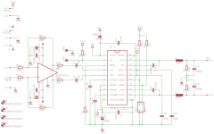
I want to have some TPA3122 pcb's professionally made.
The TPA3122 is in BTL configuration and used in combination with a THS4131 fully differential opamp in order to perform single ended to balanced conversion.
Because I'm quite new to electronics I'd like to have experienced people to take a look at my schematic and future board layout, before I spend money on boards that won't work in a desirable fashion.
Also: should I connect the power ground of the 24V for the amp with the power ground of the +-15V for the opamp?
The schmematic is attached. Thanks in advance for your advice.
Attachments
Möter said:The TPA3122 is in BTL configuration and used in combination with a THS4131 fully differential opamp in order to perform single ended to balanced conversion.
Möter!!!!!!!!!!!!!!!!

I just started a layout for this exact same thing! Mine is going to be slightly different; if it even works at all. If it does work, then I will have the board powered with a single rail for both IC's AND it will be DC coupled.

EDIT: BTW, why not use the TPA3106D1 instead? This way you only need one IC.
The only reason I'm trying the THS4131 + TPA3122D2 is because I have quite a bit of them.
HAHAHAHA What an coincidence.
That sounds really good, I was already wondering how to get dual 15V rails from a 24V supply.
I'm not using the TPA3106D1, because I haven't yet SMD soldered in my life, so I don't want to start with something more difficult than 0805 and SOIC packages (which are probably hard enough).
That sounds really good, I was already wondering how to get dual 15V rails from a 24V supply.
I'm not using the TPA3106D1, because I haven't yet SMD soldered in my life, so I don't want to start with something more difficult than 0805 and SOIC packages (which are probably hard enough).
theAnonymous1 said:Well, without getting into a debate about Tripath vs. TI ...
Pitfall nimbly avoided, sir
- thanks for the infoEva said:Put a capacitor across the filament, an inductor in series and apply a square wave. The waveform at the filament will be sine like. You will have to choose component values carefully so that the LC filter removes enough high frequency components and the filament resistance when hot provides enough damping to the filter. That's all. Electronic ballasts for fluorescent lamps work much in the same way.
If I were doing a filament supply from scratch, yeah like you said...
I assume you mean something like Pete Millet's design? I do not
have those sort of ballast drivers readily overflowing my bench.
I got buckets of prototype Class-D's that for one reason or other
weren't deemed perfect enough to ship, but might still light up an
old transmitter tube or two? I hate seeing them go to waste. The
alternative is to destroy them some other way. They can't leave,
and I got far more than I can ever use for "normal" test purposes.
Even if this works, I probably couldn't show you anything but the
filaments without permission... Kinda pointless experiment really.
I'm just a pass/fail production test monkey with a procedure to
follow. Not any sort of an actual engineer yet. Some of my own
ideas are far-out and half-baked to say the least. They don't give
me a lot of spare time to do any real damage.
IC question
What is the chip you are using as the phase inverter chip in your schematic ?
Möter said:Hello guys,
I want to have some TPA3122 pcb's professionally made.
The TPA3122 is in BTL configuration and used in combination with a THS4131 fully differential opamp in order to perform single ended to balanced conversion.
Because I'm quite new to electronics I'd like to have experienced people to take a look at my schematic and future board layout, before I spend money on boards that won't work in a desirable fashion.
Also: should I connect the power ground of the 24V for the amp with the power ground of the +-15V for the opamp?
The schmematic is attached. Thanks in advance for your advice.
What is the chip you are using as the phase inverter chip in your schematic ?
kenpeter said:
If I were doing a filament supply from scratch, yeah like you said...
I assume you mean something like Pete Millet's design? I do not
have those sort of ballast drivers readily overflowing my bench.
I got buckets of prototype Class-D's that for one reason or other
weren't deemed perfect enough to ship, but might still light up an
old transmitter tube or two? I hate seeing them go to waste. The
alternative is to destroy them some other way. They can't leave,
and I got far more than I can ever use for "normal" test purposes.
Even if this works, I probably couldn't show you anything but the
filaments without permission... Kinda pointless experiment really.
I'm just a pass/fail production test monkey with a procedure to
follow. Not any sort of an actual engineer yet. Some of my own
ideas are far-out and half-baked to say the least. They don't give
me a lot of spare time to do any real damage.
Of course you can use those class D amplifiers to drive the filaments, probably not at 50Khz, but slightly above 20Khz it should work fine.
I made new TPA3122D2 BTL boards, this time including a DRV134 to do single to balanced conversion. The DRV134 is running from the same single supply as the amp.
I like to try and use parts I already have if at all possible, so I went a little crazy with 1uF 100V X7R. There are 20 of them per board.
I like to try and use parts I already have if at all possible, so I went a little crazy with 1uF 100V X7R. There are 20 of them per board.
An externally hosted image should be here but it was not working when we last tested it.
An externally hosted image should be here but it was not working when we last tested it.
luka said:why not use ...20d2, since it performs the same if not better and more power from it?
Well, the only reason I messed with the 22D2 at all was because I have >100pcs of them and they are easy to play with since they are PDIP.
For surface mount package like the 20D2 I think the 06D1 is a better choice; like the board I made earlier in this thread. It doesn't require an external IC for BTL operation.
The above boards can swing ~11.5Vrms into 4R @ 20hz right before the over-current protection kicks in. That's around ~33W, which isn't too bad.
luka said:Why do you need them so much?
I don't need them at all. They end up sitting on a shelf after I build them.

Some people paint as a sort of therapy; I build small electronic devices I have no use for.
luka said:HAHA they really much have been cheap
Cheaper than the 99USD Texas Instruments charges for an eval board.
I think I've just learned why a high PSRR closed loop system is better in some (all?) situations.
I've had a 41hz AMP32 running the front door speakers in my car for a few weeks while I make a DIY head unit. I replaced the AMP32 with these TPA boards and there was major alternator noise through the speakers. I knew it couldn't be a ground loop because there was only the two power wires hooked up and the source was a portable device; plus the AMP32 never had this problem.
I made a CLC filter of 6,800uF -> large toroidal inductor (?mH) -> 6,800uF and the noise completely went away.
- Status
- This old topic is closed. If you want to reopen this topic, contact a moderator using the "Report Post" button.
- Home
- Amplifiers
- Class D
- My TPA3122D2N BTL proto