Solder the thermal pad.
Easiest way to do it is to buy some thermal paste (get some "Mechanic" brand SnPb off eBay, it's treated me well), paste the footprint as shown around 7:30 in this video:
https://www.youtube.com/watch?v=M_rO6oPVsws
Place the part (don't put it on backwards!)... and in all seriousness, use a frying pan on the stovetop. Put the burner on low, let it soak up heat for a couple minutes, then turn the heat up to medium until the solder melts. After the solder's been molten for about 10 seconds, kill the heat.
If you've got an IR thermometer, watch the surface temperature of the PCB with it and try to approximate a reflow temperature curve.
can you share eagle files, i use v5.
This was designed with Eagle v7.6.0, not sure if the files will be compatible with an older Eagle version?
Anyway, I was planning to share the files, but was going to wait until the actual boards came back and I had a chance to test. There could be some bugs still!
Also, I ordered 10 boards in the first manufacturing run, but I don't need that many. So if you want to help with the testing, I can mail you a couple when I get them, if you cover the shipping cost.
If you still want the files right now, let me know via PM, and I'll send them. But I'd prefer to wait until they are tested/verified before publicly posting.
yes I take two boards. PM me your paypal name. I'm pretty good at testing / debug first article boards.
Have to re-draw , the Cadsoft made a big change so not compatible. I wanted the files to add more integration with a soft input limiter and work on the "heat sink".
Easiest way to do it is to buy some thermal paste (get some "Mechanic" brand SnPb off eBay, it's treated me well), paste the footprint as shown around 7:30 in this video:
https://www.youtube.com/watch?v=M_rO6oPVsws
(...)
Thank you Gary, that's extremely helpful. In fact the video makes it look pretty easy. Far less worried now about ruining $5 tpa3118 chips.
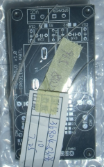
In other news, Elecrow just sent me an email letting me know the boards have shipped. Even included a picture! (Too much covered up though, mostly just a tease.)
Attachments
matt , I used these on the cheapo ebay boards, make a big T difference, don't think anything else is necessary.
http://www.diyaudio.com/forums/clas...ng-them-everything-comes-120.html#post4785015
-
http://www.diyaudio.com/forums/clas...ng-them-everything-comes-120.html#post4785015
-
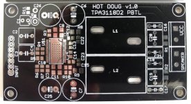
You'll spend half an hour with that card in your hands, sizing it up, marveling at yourself thinking "I MADE THIS!"... enjoy the moment")
Indeed, I just received them! (To be honest I started the marveling with that picture Elecrow sent before they shipped.
)I just ordered the actual tda3118 chips, so need to wait before I can attempt to solder them.
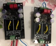
I did a quick sanity check with the continuity meter, no obvious problems (e.g. no short between VCC and GND).
Although, already I think I didn't pay close enough attention to the package size of some of the through-hole components. I'm afraid some spaces might be smaller than the part I wanted to use. But, we'll see when I get all the parts!
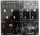
(Shiny black boards are kind of hard to photograph. You can see the reflection of me holding my phone in the pic with two boards!)
Attachments
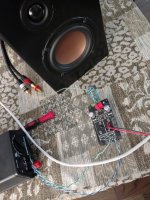
They actually work!
Good news and bad news.
Bad news: I accidentally ordered Mechanic brand "Conductive Silver Paint" instead of solder paste. Didn't realize that until after I tried soldering the tpa3118 chip via frying pan... I basically shorted all the pins on the chip.
I couldn't wait for another shipment of the right stuff all the way from China, as I'm in the middle of a kid-free vacation. So I thought I'd try the skillet method but with regular old solder. I basically "painted" the pin pads with solder, then put a big blob where the chip thermal pad goes. I painted the whole thing with a thick layer of flux gel. I put the chip in the right spot, then secured it with Kapton tape.
I threw it on the skillet, cranked up the heat, then used my tweezers to keep pushing down on the chip until I felt the solder melt, and the chip touched down on the PCB. Left it there for a few seconds, killed the heat.
The job actually looked reasonable to my naked eye. No obvious solder bridges, and all the chip pins appeared to be secure.
No way to test until most of the rest of the board is stuffed, so I just got to it.
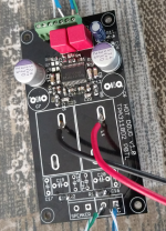
Good news: the board actually works! You can see in the picture I didn't populate any of the output filter. I'm just now ordering the inductors and other output filter parts. (I was trying to save a little money in case these boards didn't work.)
But, at any rate: I used my cell phone as a source, and fed the amp 9V from an adjustable power supply. No pops, hisses, smoke or any other bad stuff, just music!
So now I'll have to stuff a second board so I can actually have a stereo pair. And wait for the output filter parts.
Thanks again for all the help everyone!
Good news and bad news.
Bad news: I accidentally ordered Mechanic brand "Conductive Silver Paint" instead of solder paste. Didn't realize that until after I tried soldering the tpa3118 chip via frying pan... I basically shorted all the pins on the chip.
I couldn't wait for another shipment of the right stuff all the way from China, as I'm in the middle of a kid-free vacation. So I thought I'd try the skillet method but with regular old solder. I basically "painted" the pin pads with solder, then put a big blob where the chip thermal pad goes. I painted the whole thing with a thick layer of flux gel. I put the chip in the right spot, then secured it with Kapton tape.
I threw it on the skillet, cranked up the heat, then used my tweezers to keep pushing down on the chip until I felt the solder melt, and the chip touched down on the PCB. Left it there for a few seconds, killed the heat.
The job actually looked reasonable to my naked eye. No obvious solder bridges, and all the chip pins appeared to be secure.
No way to test until most of the rest of the board is stuffed, so I just got to it.
Good news: the board actually works! You can see in the picture I didn't populate any of the output filter. I'm just now ordering the inductors and other output filter parts. (I was trying to save a little money in case these boards didn't work.)
But, at any rate: I used my cell phone as a source, and fed the amp 9V from an adjustable power supply. No pops, hisses, smoke or any other bad stuff, just music!
So now I'll have to stuff a second board so I can actually have a stereo pair.
And wait for the output filter parts.Thanks again for all the help everyone!
Attachments
You don't need an output filter if your connections are short and your speakers have enough self inductance. ( They mostly will if they aren't just 1" full range)
Quiescent current is a bit higher, but not that much.
So if mounted within the speakers, you may skip that expensive filter parts at all with best possible sound.
Nice work so far.
Quiescent current is a bit higher, but not that much.
So if mounted within the speakers, you may skip that expensive filter parts at all with best possible sound.
Nice work so far.
Looks great. Congrats on the successful design/build.
Next time you fire up the skillet, don't worry about using Kapton tape to solder down the TPA. The surface tension of molten solder will pull components straight on their footprints. Which is something I appreciate personally, my reflowed cards look oh so much better than the old hand-assembled Wiener cards which have the parts half crooked
Next time you fire up the skillet, don't worry about using Kapton tape to solder down the TPA. The surface tension of molten solder will pull components straight on their footprints. Which is something I appreciate personally, my reflowed cards look oh so much better than the old hand-assembled Wiener cards which have the parts half crooked
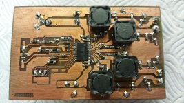
Jasper, you made your own PCB, with a 0.65mm pin spacing footprint on it no less. You put us to shame
+1.
I am indeed quite happy with how my boards turned out. But 99% of the credit goes to this community. The circuit I literally copied verbatim from DUG's boards (just added a couple caps), and the layout was mostly just a tweaking of DUG's design as well. And most of the tweaks were suggestions from community members!
It's fun (for me anyway) to go through this thread and just look at all the pictures I posted, to see the board design "evolve" as I worked on it.
- Status
- This old topic is closed. If you want to reopen this topic, contact a moderator using the "Report Post" button.
- Home
- Amplifiers
- Class D
- My tpa3118 board - comments/critiques?