Also known as the "Death Of the Staircase". My previous design was called "The Staircase", so I thought of putting it to an end.  This is the 3rd reconstruction of the amplifier with mostly the same parts, but a new chassis. The reason for rebuilding the old and not making a new is because it's cheaper - not having to buy entirely new parts. Afterwards it's my first and it will always be my amplifier for learning and practicing.
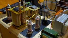
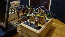
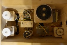
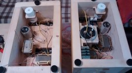
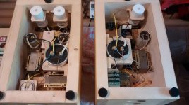
This version has improved chassis - rigid, very thick pine wood; coupling - interstage transformer 1:1; power supply - RIFA PEH169 high grade capacitors.
It is not completed yet. I have to build transformer housings, put black plate screws, tube top cap insulation and... I'm also winding hi-fi low Cp and low DCR psu chokes and maybe I'll do a higher grade power transformer. I'm very tempted to try regulation, maybe salas SSHV for the driver stage and "something else"for the output stage.
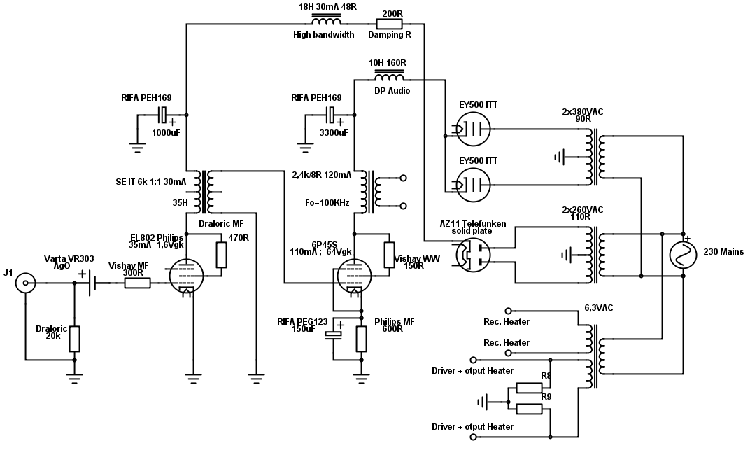
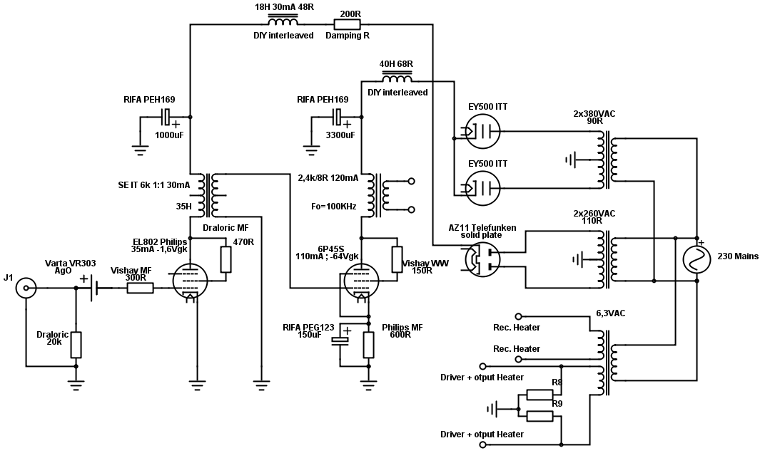
Every component is described in the schematic right here! It says it all.
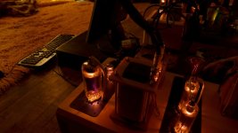
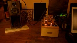
I'm very happy with the result - smooth, liquid, live sound that makes you go into extasy right away. The bass is a little slow and I guess the high PSU DCR is to blame, this is why I'm tempted for the regulation. Ideas never stop.
The power output is 11W. There are no power switches. The power cords are Neotech 3PS25 terminated with Valab rhodium IEC and plug. There is a separate power cord for the heaters.
Enjoy the pics. I'll shoot some more in a more thorough way these days.
This is the 3rd reconstruction of the amplifier with mostly the same parts, but a new chassis. The reason for rebuilding the old and not making a new is because it's cheaper - not having to buy entirely new parts. Afterwards it's my first and it will always be my amplifier for learning and practicing.This version has improved chassis - rigid, very thick pine wood; coupling - interstage transformer 1:1; power supply - RIFA PEH169 high grade capacitors.
It is not completed yet. I have to build transformer housings, put black plate screws, tube top cap insulation and... I'm also winding hi-fi low Cp and low DCR psu chokes and maybe I'll do a higher grade power transformer. I'm very tempted to try regulation, maybe salas SSHV for the driver stage and "something else"for the output stage.
Every component is described in the schematic right here! It says it all.
I'm very happy with the result - smooth, liquid, live sound that makes you go into extasy right away
. The bass is a little slow and I guess the high PSU DCR is to blame, this is why I'm tempted for the regulation. Ideas never stop.The power output is 11W. There are no power switches. The power cords are Neotech 3PS25 terminated with Valab rhodium IEC and plug. There is a separate power cord for the heaters.
Enjoy the pics. I'll shoot some more in a more thorough way these days.
Attachments
-
 P1070494.JPG727.3 KB · Views: 1,981
 -
 P1070507.JPG647.9 KB · Views: 875
 -
 P1070504.JPG665.7 KB · Views: 651
 -
 P1070501.JPG585.1 KB · Views: 454
 -
 P1070497.JPG536.5 KB · Views: 514
 -
 P1070489.JPG703.7 KB · Views: 539
 -
 P1070482.JPG706 KB · Views: 1,628
 -
 P1070479.JPG826.5 KB · Views: 1,712
 -
 P1070474.JPG774.1 KB · Views: 1,765
 -
 P1070470.JPG619.3 KB · Views: 1,790
Last edited:

Hello again, how are you?
I'm doing some upgrades. I bought new power transformers intended for total choke input conversion - 450VAC CT for the power stage and one 270CT for the driver stage. My filament transformer is of course - separate.
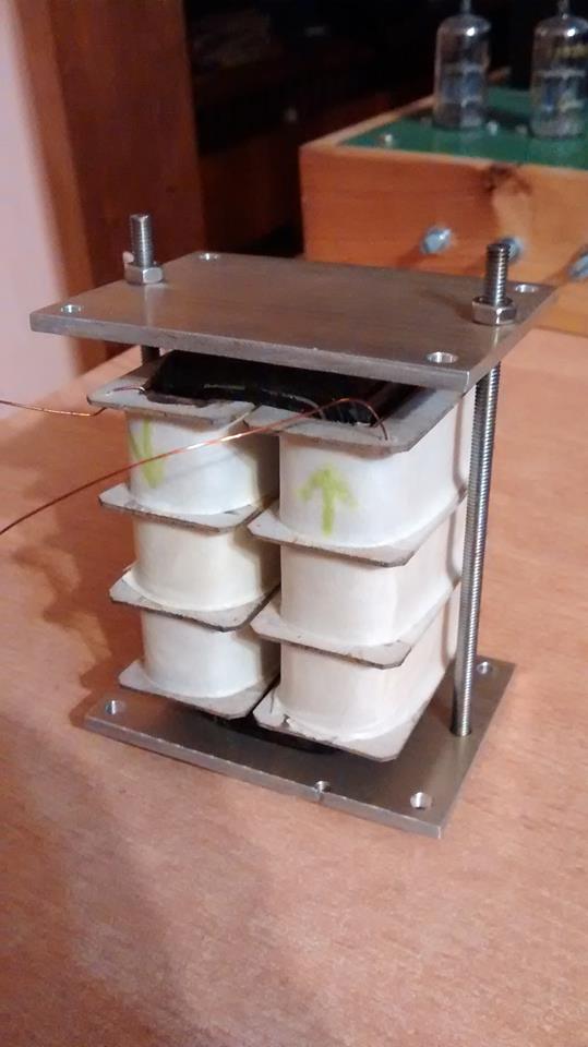
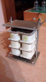
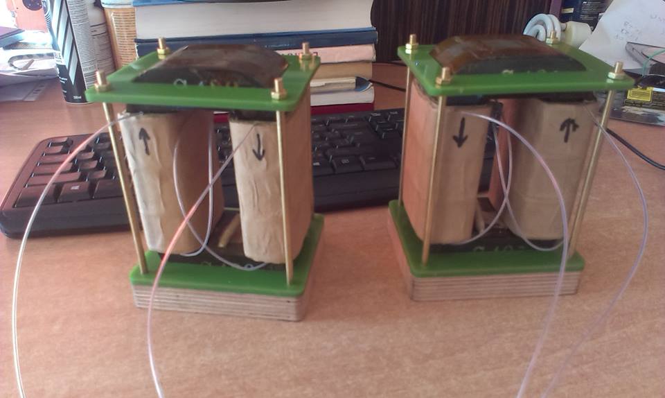
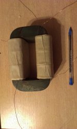
I haven't wound all my high-bandwidth PSU chokes yet, but I make a progress. Here's one of them for the driver stage.
Measured resonance frequency: 25KHz
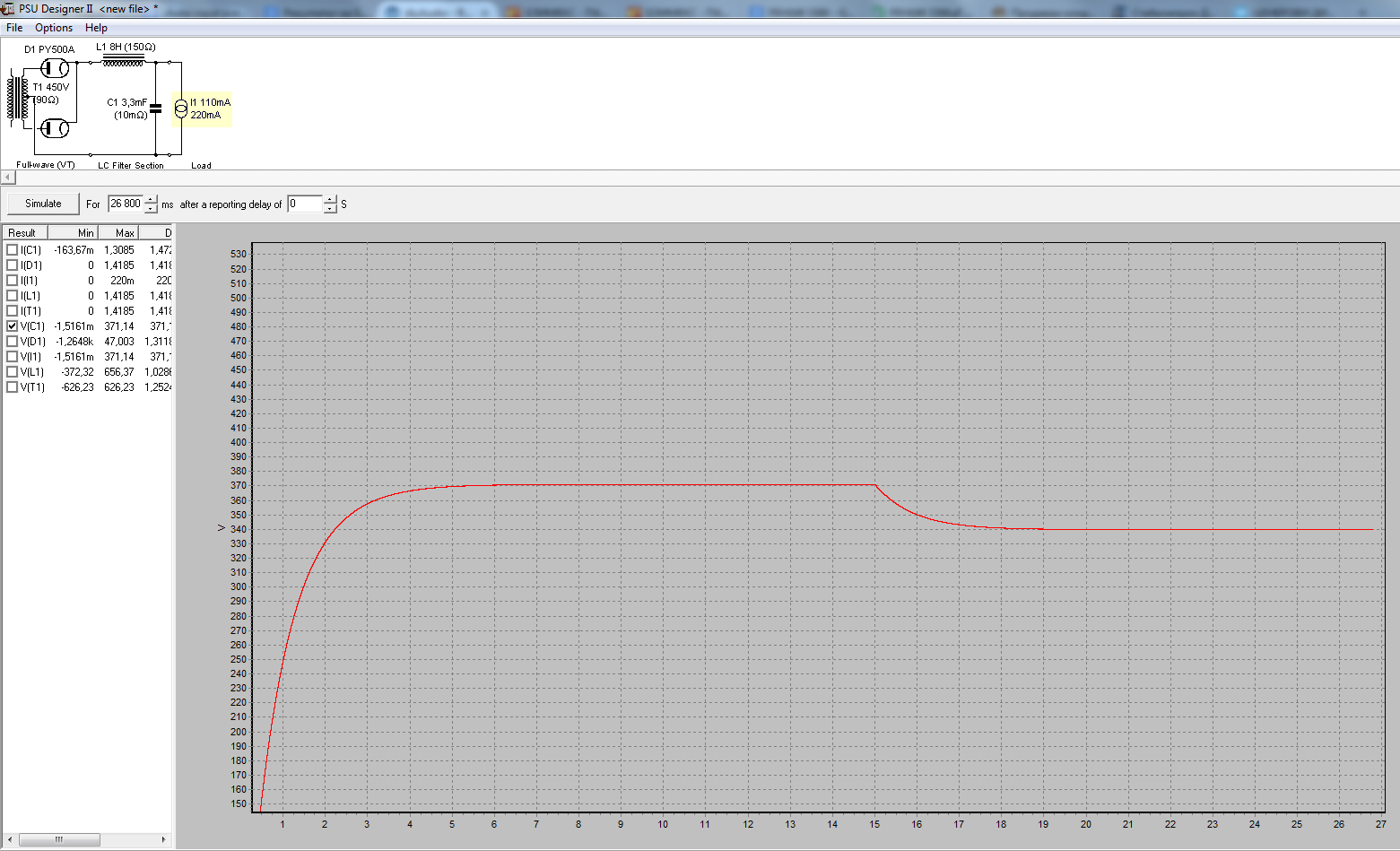
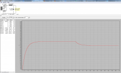
Here's a quick simulation of the power stage PSU using PSUD. Approx 1,4mV or ripple will appear on the speaker output.
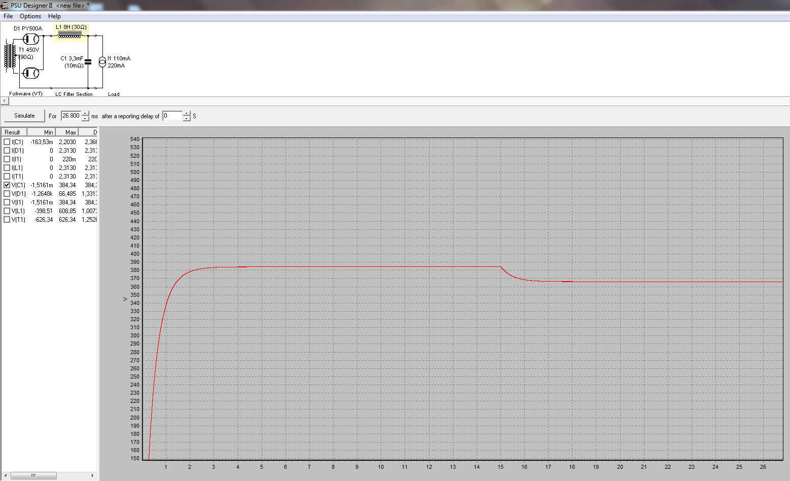
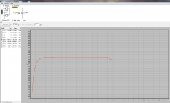
Here's the power stage simulation again, but with a higher-fi low DCR choke I plan winding. The tube rectifier and transformer resistances are high enough to dampen the Q.
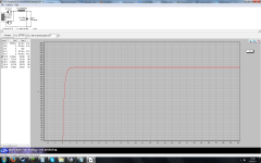
And here's the driver PSUD simulation that will preceded a Salas SSHV2. I think I will benefit very much from good regulation, especially on the driver stage.

My shunt reg. boards are almost ready, I'm waiting for a Dale RN55 resistor shipment. Right now I'm working on an overvoltage protection circuit for the power stage PSU.
See you later.!
I'm doing some upgrades. I bought new power transformers intended for total choke input conversion - 450VAC CT for the power stage and one 270CT for the driver stage. My filament transformer is of course - separate.
I haven't wound all my high-bandwidth PSU chokes yet, but I make a progress. Here's one of them for the driver stage.
Measured resonance frequency: 25KHz
Here's a quick simulation of the power stage PSU using PSUD. Approx 1,4mV or ripple will appear on the speaker output.
Here's the power stage simulation again, but with a higher-fi low DCR choke I plan winding. The tube rectifier and transformer resistances are high enough to dampen the Q.
And here's the driver PSUD simulation that will preceded a Salas SSHV2. I think I will benefit very much from good regulation, especially on the driver stage.
My shunt reg. boards are almost ready, I'm waiting for a Dale RN55 resistor shipment. Right now I'm working on an overvoltage protection circuit for the power stage PSU.
See you later.!
Attachments
Last edited:
Today I fired the first monoblock with the new upgrades. Or I mean, successfully turned on! I'm very happy. With the new power transformer with electrostatic screen, I measure a very low leakage with my DMM. The tubes are working in the following settings.
6P45S output tube
Vgk = -69V
Va = 327V
B+ = 400V
Ia = 115mA
Pd = 39.2W
Pout = to measure.
EL802 driver tube
Vgk = -1,92
Va = 178V
B+ = 185V
Ia = 23mA
Pd = 4.1W
Gain ~60 at 100Hz, 53 at 25Hz, (IT loaded)
u = 68
Input sensitivity (on paper) ~ 820Vrms
Power supply components:
(split power supply rails, choke input topology)
-Power transformer for anode voltages: secondariess 2*475V CT 90R + 2*280V CT 100R ; electrostatic screen ; primary inductance - 22H
-Power transformer for heater voltages: secondaries 1*6.3 + 1*6.3 at 4.6A ; no electrostatic screen ; model - russian ТН 127-220 (to be upgraded)
-Rectifier for the driver stage: AZ11 Telefunken solid plate
-Rectifier for the output stage: 2* EY500a ITT Lorenz
-Filter choke on the driver stage ; simple wound on unknown EI core, 240Rdc, 15H at 150mA (to be upgraded with high bandwith, low Rdc choke)
-Filter choke on the output stage ; simple wound on unknown EI core, 150Rdc, 10H at 200mA (to be upgraded with high bandwith, low Rdc choke)
-Main driver stage filter capacitor - RIFA PEH169 470uF 450Vdc
-Main output stage filter capacitor - RIFA PEH169 3300uF 450Vdc
-Driver stage B+ regulator - SALAS SSHV shunt regulator with DALE RN55 resistors ; output capacitor Mundorf MKP 10uF ; Vref filter capacitor RIFA PME271 ; dissipation 65mA at 185Vout
-Hookup wire: Neotech UP-OCC copper with determined by ear direction.
-420V Zener string output stage capacitor overvoltage protection.
Amplifier stages components:
Driver stage:
-EL802 Philips triode strapped, 1k 1/4W MF Draloric resistor to G2 ; G3 to K
-G1 series resistor: Ohmite 900R 1/2W carbon comp soldered at the socket
-Input resistor: Philips 20k MF 1/4W G1 to GND
-Hookup wire: Neotech UP-OCC covered in cotton.
-Socket: Valab teflon gold pin
-Cathode resistor: Philips 84,5R MF 1/4W (to be upgraded)
-Cathode capacitor: RIFA PEH169 1500uF 200V
-Interstage transformer on TC-80 russian core 1:1 ; Z=6k at 25Hz
Output stage:
-6P45S Svetlana triode strapped ; 180R Vishay Sfernice RB59 wirewound 3W to G2 ; G3 to K
-No grid series resistor, no interstage secondary loading resistor
-Cathode resistor:4*2,4k = 600R Philips metal oxide resistor 20W (to be upgraded, Mills maybe)
-Cathode capacitor: RIFA PEG124 150uF 200V
-Output transformer: 2,4k/8R wound on TC-280 russian core.
-Socket: russian ceramic brass pin
Misc:
-Chassis material: white pine massive 40mm thick wood ; 4mm anodized aluminum socket plates.
-RCA input: RJ-133ST rhodium plated copper KaCsa
-Speaker output terminals: BP-252G gold plated copper Neotech
-Star ground topology + safety ground
-Double IEC: PC-1249G Gold plated KaCsa
-Non magnetic brass and SS mounting screws
-Soundcare feet
-Heater referenced to GND with 2*40R artificial center tap
-Made with great love and desire
Best regards!
I'm very happy. With the new power transformer with electrostatic screen, I measure a very low leakage with my DMM. The tubes are working in the following settings.6P45S output tube
Vgk = -69V
Va = 327V
B+ = 400V
Ia = 115mA
Pd = 39.2W
Pout = to measure.
EL802 driver tube
Vgk = -1,92
Va = 178V
B+ = 185V
Ia = 23mA
Pd = 4.1W
Gain ~60 at 100Hz, 53 at 25Hz, (IT loaded)
u = 68
Input sensitivity (on paper) ~ 820Vrms
Power supply components:
(split power supply rails, choke input topology)
-Power transformer for anode voltages: secondariess 2*475V CT 90R + 2*280V CT 100R ; electrostatic screen ; primary inductance - 22H
-Power transformer for heater voltages: secondaries 1*6.3 + 1*6.3 at 4.6A ; no electrostatic screen ; model - russian ТН 127-220 (to be upgraded)
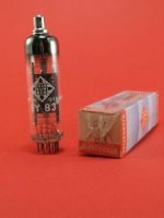
-Rectifier for the driver stage: AZ11 Telefunken solid plate
-Rectifier for the output stage: 2* EY500a ITT Lorenz
-Filter choke on the driver stage ; simple wound on unknown EI core, 240Rdc, 15H at 150mA (to be upgraded with high bandwith, low Rdc choke)
-Filter choke on the output stage ; simple wound on unknown EI core, 150Rdc, 10H at 200mA (to be upgraded with high bandwith, low Rdc choke)
-Main driver stage filter capacitor - RIFA PEH169 470uF 450Vdc
-Main output stage filter capacitor - RIFA PEH169 3300uF 450Vdc
-Driver stage B+ regulator - SALAS SSHV shunt regulator with DALE RN55 resistors ; output capacitor Mundorf MKP 10uF ; Vref filter capacitor RIFA PME271 ; dissipation 65mA at 185Vout
-Hookup wire: Neotech UP-OCC copper with determined by ear direction.
-420V Zener string output stage capacitor overvoltage protection.
Amplifier stages components:
Driver stage:
-EL802 Philips triode strapped, 1k 1/4W MF Draloric resistor to G2 ; G3 to K
-G1 series resistor: Ohmite 900R 1/2W carbon comp soldered at the socket
-Input resistor: Philips 20k MF 1/4W G1 to GND
-Hookup wire: Neotech UP-OCC covered in cotton.
-Socket: Valab teflon gold pin
-Cathode resistor: Philips 84,5R MF 1/4W (to be upgraded)
-Cathode capacitor: RIFA PEH169 1500uF 200V
-Interstage transformer on TC-80 russian core 1:1 ; Z=6k at 25Hz
Output stage:
-6P45S Svetlana triode strapped ; 180R Vishay Sfernice RB59 wirewound 3W to G2 ; G3 to K
-No grid series resistor, no interstage secondary loading resistor
-Cathode resistor:4*2,4k = 600R Philips metal oxide resistor 20W (to be upgraded, Mills maybe)
-Cathode capacitor: RIFA PEG124 150uF 200V
-Output transformer: 2,4k/8R wound on TC-280 russian core.
-Socket: russian ceramic brass pin
Misc:
-Chassis material: white pine massive 40mm thick wood ; 4mm anodized aluminum socket plates.
-RCA input: RJ-133ST rhodium plated copper KaCsa
-Speaker output terminals: BP-252G gold plated copper Neotech
-Star ground topology + safety ground
-Double IEC: PC-1249G Gold plated KaCsa
-Non magnetic brass and SS mounting screws
-Soundcare feet
-Heater referenced to GND with 2*40R artificial center tap
-Made with great love and desire
Best regards!
Last edited:
Hello again guys,
Some time has passed and I've done little, but very influential stuff with sound improvement. I
-changed the input choke from the driver's stage power supply with a higher grade C core, higher bandwidth interleaved choke. The sound difference was astonishing. In therms of sound, I gained some of everything - attack, transparency, speed, detail, emotion, PRAT.
-removed the Salas SSHV. Somehow it didn't work for me, even after 100h of burn in. Although it delivers some speed, slam and gives more order to the soundstage, it gives a little of a harsh, unpleasant, SS like signature to the sound. Or maybe it didn't shake hands well with my interstage transformer's inductance. Although I couldn't measure any signs of oscillation.
There is no audible hum even with one LC stage the driver's PSU.
-moved from cathode bias to battery bias. I also became convinced that alcaline batteries in the grid sound horrible. But then I bought a Varta silver oxide battery. Man, this one delivers the goods. My reference was a Blackgate NX in the cathode with the same bias. The SO battery needs to settle a bit, but after some burn in, it rocks. It wins for me, because it's much less expensive than a BG NX.
I also did build some higher-end battery holders from indian rosewood with Neotech UP-OCC wire directly pressured on the terminals.
Some upgrades I would like to do next:
1. Change the power's stage power supply choke with a higher grade, higher bandwidth C-core choke.
2. Move to power stage fixed bias, but building it with a very high quality PSU - tube rectified, LCRC
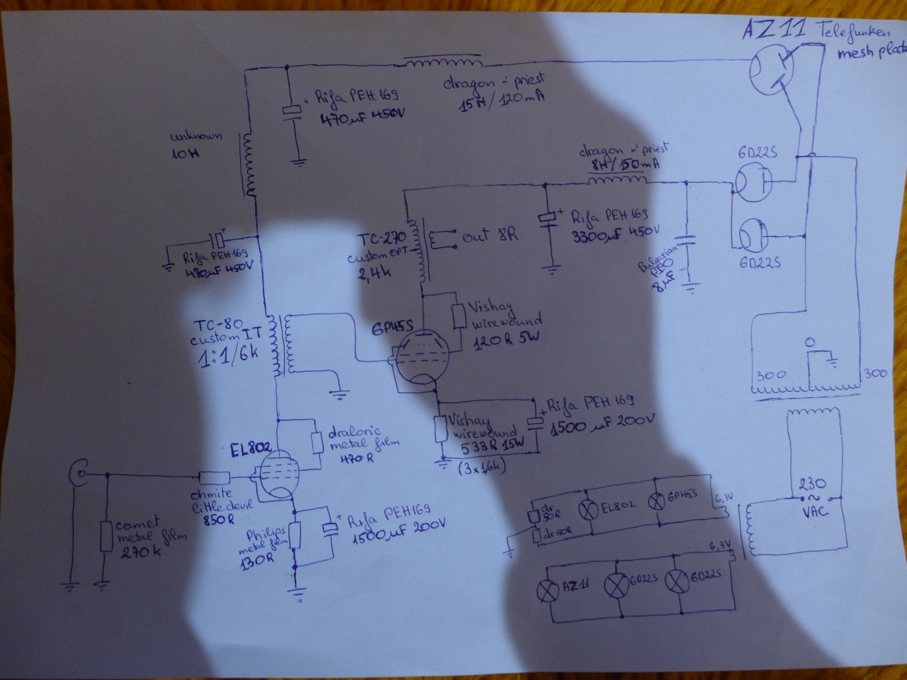
Current schematic.
Some time has passed and I've done little, but very influential stuff with sound improvement. I
-changed the input choke from the driver's stage power supply with a higher grade C core, higher bandwidth interleaved choke. The sound difference was astonishing. In therms of sound, I gained some of everything - attack, transparency, speed, detail, emotion, PRAT.
-removed the Salas SSHV. Somehow it didn't work for me, even after 100h of burn in. Although it delivers some speed, slam and gives more order to the soundstage, it gives a little of a harsh, unpleasant, SS like signature to the sound. Or maybe it didn't shake hands well with my interstage transformer's inductance. Although I couldn't measure any signs of oscillation.
There is no audible hum even with one LC stage the driver's PSU.
-moved from cathode bias to battery bias. I also became convinced that alcaline batteries in the grid sound horrible. But then I bought a Varta silver oxide battery. Man, this one delivers the goods. My reference was a Blackgate NX in the cathode with the same bias. The SO battery needs to settle a bit, but after some burn in, it rocks. It wins for me, because it's much less expensive than a BG NX.
I also did build some higher-end battery holders from indian rosewood with Neotech UP-OCC wire directly pressured on the terminals.
Some upgrades I would like to do next:
1. Change the power's stage power supply choke with a higher grade, higher bandwidth C-core choke.
2. Move to power stage fixed bias, but building it with a very high quality PSU - tube rectified, LCRC
Current schematic.
Attachments

Last edited:
The AZ11 is a directly heated rectifier tube with 4V filaments. If you power it from a 6.3 V winding according to your schematic, you need an additional power resistor in series with the AZ11 filament to drop the filament voltage (approx. 2 Ohms are required) - otherwise the lifetime of the AZ11 will be very low.
Hello again,
I did upgrade the power supply section with another choke. 40H at 68RdC at 130mA, custom wound and interleaved - on a Japanese 11sq/cm C core.
The benefits of a better choke are again obvious - subjectively more realism where it comes to microdetail and attack. Cleaner sounds and lesser subjective intermodulation - better separation. In terms of soundstage - better separation, more stage width and more realistic images.
I am pretty happy with the upgrade and more comes.
I will try swapping the damper diodes with others: 6AU4GTA whom I got from a friend.
Later I need to upgrade my filament transformer with better engineered ones - less flux density, less mechanical noise and electrostatic shielding.
Finally I will opt for a fixed bias for the output tube that will be very high-end-ish. Separate well made transformer, followed by a tube rectifier and a choke input LC, then RC. A high grade choke will be built and good capacitors must be used.
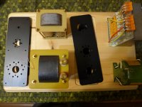
These are the babies:
And this is the current schematic:
Regards,
Alexander.
I did upgrade the power supply section with another choke. 40H at 68RdC at 130mA, custom wound and interleaved - on a Japanese 11sq/cm C core.
The benefits of a better choke are again obvious - subjectively more realism where it comes to microdetail and attack. Cleaner sounds and lesser subjective intermodulation - better separation. In terms of soundstage - better separation, more stage width and more realistic images.
I am pretty happy with the upgrade and more comes.
I will try swapping the damper diodes with others: 6AU4GTA whom I got from a friend.
Later I need to upgrade my filament transformer with better engineered ones - less flux density, less mechanical noise and electrostatic shielding.
Finally I will opt for a fixed bias for the output tube that will be very high-end-ish. Separate well made transformer, followed by a tube rectifier and a choke input LC, then RC. A high grade choke will be built and good capacitors must be used.
These are the babies:
And this is the current schematic:
Regards,
Alexander.
Attachments


While I'm on holydays these few days, I did a resistor upgrade. Small I thought, but WOOW! I'm currently very happy with the sound my amps output.
The two resistors I upgraded are:
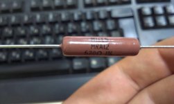
1. Cathode Philips metal film paralleled resistors with MILLS MRA12 wirewound
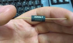
2. Grid resistor from generic Vishay metal film to Amtrans carbon film
1. The WOW suprise here was the soundstage. I gained depth, width and larger size of musical instruments. The resistor has a smooth, peaceful signature, but doesn't squash dynamics. Subjectively, its installation sounded like you evened the FR of a speaker - no peaks and dips.
2. A naturalness was immediately apparent when installing the Amtrans. At first, it gave me the impression to be more even than my taste. After some listening and burn in, I heard a much better soundstaging while there was very good low level information, sometimes not possible for carbon resistors. Effortless and very musical sound.
Finally, the two resistor swap made me listen to half of my musical collection with a smile on my face.
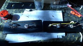
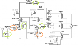
I'm attaching some photos. The orange circles represent the upgraded positions, while the green ones will be upgraded, soon I hope.
I'm currently very happy with the sound my amps output. The two resistors I upgraded are:
1. Cathode Philips metal film paralleled resistors with MILLS MRA12 wirewound
2. Grid resistor from generic Vishay metal film to Amtrans carbon film
1. The WOW suprise here was the soundstage. I gained depth, width and larger size of musical instruments. The resistor has a smooth, peaceful signature, but doesn't squash dynamics. Subjectively, its installation sounded like you evened the FR of a speaker - no peaks and dips.
2. A naturalness was immediately apparent when installing the Amtrans. At first, it gave me the impression to be more even than my taste. After some listening and burn in, I heard a much better soundstaging while there was very good low level information, sometimes not possible for carbon resistors. Effortless and very musical sound.
Finally, the two resistor swap made me listen to half of my musical collection with a smile on my face.
I'm attaching some photos. The orange circles represent the upgraded positions, while the green ones will be upgraded, soon I hope.
Attachments
-
 6P45S-2.png75.8 KB · Views: 539
 -
 12804817_1143649522335287_865695472876650644_n.jpg71 KB · Views: 525
 -
 12705506_1143649775668595_5174398602034460205_n.jpg41.1 KB · Views: 528
 -
 10391541_1143649852335254_7048219467864498799_n.jpg43.5 KB · Views: 519
 -
 8283_1143649672335272_4964471342231108058_n.jpg19.7 KB · Views: 508
It's been a long time I didn't do many upgrades, but life has become poorer here. I managed to swap the ITT EY500 damper diodes for Telefunken EY83s. I think I won't go back to the ITTs. I'm very happy with the EY83s.

I have also come to the problem where my heater transformers started to buzz. I suspect it is because of overloading and the buzz is very apparent during the day. I think the presence of DC on the heavily loaded mains drives them into saturation. They do calm down during night.
So I wound new transformers on a larger double C core, but I have no spare time to install them. They have 2 secondaries 6.3V at 5A and an electrostatic shield.
After installing them, I will be trying fixed bias on the output stage. High-end bias like it should be - tube rectification followed by LCRC filtering.
Attachments
Last edited by a moderator:
Hello,
I had to move to another home recently, so I didn't have any free time available. Things are going well now and this week-end hopefully I'll have some free time for working on the amp. I'll finally install my new heater supply transformers and maybe install the ceramic anode caps I bought.
I had to move to another home recently, so I didn't have any free time available. Things are going well now and this week-end hopefully I'll have some free time for working on the amp. I'll finally install my new heater supply transformers and maybe install the ceramic anode caps I bought.
Hi 50AE
Great to see your project! PL802 in Triode looks to be a great driver.
Going from metal film in the cathode to Mills is indeed huge. For a while, Mills were difficult (at least for me) to obtain, so I experimented a bit and found this cheap 'n dirty solution:
Get a decent quality wire wound and parallel it with a decent quality carbon film. You will of course need to do some maths to arrive at the appropriate value, but the carbon film can easily be 3-5x the resistance of the wirewound. They don't need to be equal.
Of course, if you can get the exact appropriate value in a Mills then it is an excellent choice on the cathode.
Ian
soulmerchant,
EL802 is a very nice tube. The greedy side wakes inside of me, because I only bought 10 pcs and I wish I had more
About the cathode bias tips you mentioned, I might try them in my next SET project. On this one, I'll jump directly on a fixed bias implemented with good parts. Thanks for your suggestions.
I'm almost ready with the heater transformers. The mounting elements were made today. Tomorrow will be the day of their installation.
Attachments
Do you really think that swapping your beefy EY500A diodes, which were designed for colour tv sets with a deflection angle of 110°, for EY83's from 90° b/w tvs is an upgrade? No, it ain't. But indeed, your finals will benefit from this modification, due to the lower B+ voltage that is to be expected - and thus the reduced plate power dissipation, which up to then has been waaay to much (see the glowing plates in your photographs).
And do you really think that theese voodoo-ish resistors in post #11 are an improvement to your amp? Did you do some measurements to prove this claim, or blinded A-B tests? Or do you rely solely on your ears, which, of course, are objective and ab-so-lute-ly free from any bias?
Best regards!
And do you really think that theese voodoo-ish resistors in post #11 are an improvement to your amp? Did you do some measurements to prove this claim, or blinded A-B tests? Or do you rely solely on your ears, which, of course, are objective and ab-so-lute-ly free from any bias?
Best regards!
Do you really think that swapping your beefy EY500A diodes, which were designed for colour tv sets with a deflection angle of 110°, for EY83's from 90° b/w tvs is an upgrade? No, it ain't. But indeed, your finals will benefit from this modification, due to the lower B+ voltage that is to be expected - and thus the reduced plate power dissipation, which up to then has been waaay to much (see the glowing plates in your photographs).
Best regards!
The main benefit is sound that I like better. The ITTs have a bit harsh and overexposed highs, while the Telefunken EY83s give me a nice legato over the whole spectrum, coherency and a feel of more synergy. The voltage drop is 5V more approx. The plates still glow a bit and I don't mind. 6P45S is a very sturdy tube and can dissipate even more than this. I've run then on 42W Pd for 2 years with very minor emission deviation. I also have a friend who had his pair put on 50W with the plates pretty red for a few years.
And do you really think that theese voodoo-ish resistors in post #11 are an improvement to your amp? Did you do some measurements to prove this claim, or blinded A-B tests? Or do you rely solely on your ears, which, of course, are objective and ab-so-lute-ly free from any bias?
Yes, I do. I do not measure, sometimes I do blind A-B tests and I rely mostly on my ears. I'm sharing my subjective opinion. It is useful to some people. If you don't agree with my methodology, I'm not forcing you to read this thread.
The only measurements I can give you on this amp are:
Pout - 12,2W RMS before clipping
Frequency response at -3dB = 22Hz- 28kHz
Resonant frequency of the IT in this config - 33kHz.
Resonant frequency of the OT in this config - 110kHz
The rest - ears. This is my personal approach.
Best regards!
Last edited:
Hello there,
I've been lately upgrading my DAC, because I found out it had "weaker"spots in my system than my amplifier does.
Here is my schematic with some new components so far. Sonically, I preferred and replaced:
-RIFA PEH169 with NOS orange colored Siemens industrial capacitor. The NOS Siemens are so far my preferred industrial grade electrolytic capacitors, can be found for cheap and easily reformed. The later that I measured had an ESR of 0,015mOhms for a 10 000uF/100V value
-Mudorf MCAP with Bosch MP in the negative bias power supply. Bosch MP is an awesome capacitor, I love it.
-Vishay NOS wirewound with Ohmite AG series wirewound.
I also put a new pair of matched power tubes, because the left one started to weaken quite unexpectedly. Everything works fine now!
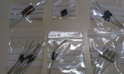
My next step would be upgrading the driver stage resistors. And finally, winding a new heater transformer for rectifier tubes like these. I got my hands on 6 of them.
Best regards,
Alexander.
I've been lately upgrading my DAC, because I found out it had "weaker"spots in my system than my amplifier does.
An externally hosted image should be here but it was not working when we last tested it.
Here is my schematic with some new components so far. Sonically, I preferred and replaced:
-RIFA PEH169 with NOS orange colored Siemens industrial capacitor. The NOS Siemens are so far my preferred industrial grade electrolytic capacitors, can be found for cheap and easily reformed. The later that I measured had an ESR of 0,015mOhms for a 10 000uF/100V value
-Mudorf MCAP with Bosch MP in the negative bias power supply. Bosch MP is an awesome capacitor, I love it.
-Vishay NOS wirewound with Ohmite AG series wirewound.
An externally hosted image should be here but it was not working when we last tested it.
I also put a new pair of matched power tubes, because the left one started to weaken quite unexpectedly. Everything works fine now!
My next step would be upgrading the driver stage resistors. And finally, winding a new heater transformer for rectifier tubes like these. I got my hands on 6 of them.
An externally hosted image should be here but it was not working when we last tested it.
Best regards,
Alexander.
Last edited:
Hello again,
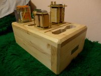
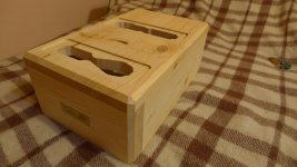
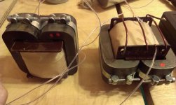
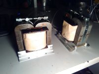
I managed to wind these babies dedicated to be my new heater transformers:
They have the following voltages:
5VAC C.T. (2.5V+2.5V) at 7A for the MV rectifiers
6.3VAC at 5A for the power and driver tubes
4VAC at 3A for the AZ11 rectifier
There are also two electrostatic shields. One between the primary and secondaries and one between the rectifier coils and amplifier tube coils.
As you may already know, the tubes need much less current, but I wanted to make full use of the magnetic core. Who knows, I might need this surplus of current in the future? The core itself is high quality G.O.S.S and it was by Imphy, a reputable French magnetic core manufacturer. It can easily be used to make a 100VA transformer.
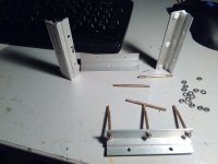
Before starting to transform my monoblocks for MV use, I also need to order socket adapters to be cut. I usually use CNC services. The material is a fiberglass composite for PCB boards, it is the same as the green transformer fasteners you have seen above.
Here is a CAD drawing of an adapter.
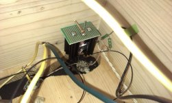
In order to gain access to the power stage psu rectifiers, I'll have to remove the big filtering capacitor encircled with yellow. Not so hard, I expected worse.
I managed to wind these babies dedicated to be my new heater transformers:
They have the following voltages:
5VAC C.T. (2.5V+2.5V) at 7A for the MV rectifiers
6.3VAC at 5A for the power and driver tubes
4VAC at 3A for the AZ11 rectifier
There are also two electrostatic shields. One between the primary and secondaries and one between the rectifier coils and amplifier tube coils.
As you may already know, the tubes need much less current, but I wanted to make full use of the magnetic core. Who knows, I might need this surplus of current in the future? The core itself is high quality G.O.S.S and it was by Imphy, a reputable French magnetic core manufacturer. It can easily be used to make a 100VA transformer.
Before starting to transform my monoblocks for MV use, I also need to order socket adapters to be cut. I usually use CNC services. The material is a fiberglass composite for PCB boards, it is the same as the green transformer fasteners you have seen above.
Here is a CAD drawing of an adapter.
In order to gain access to the power stage psu rectifiers, I'll have to remove the big filtering capacitor encircled with yellow. Not so hard, I expected worse.
Last edited:
- Status
- This old topic is closed. If you want to reopen this topic, contact a moderator using the "Report Post" button.
- Home
- Amplifiers
- Tubes / Valves
- My S.E.T remade again - the DOS