I will install my 10A fuses between caps I think... providing the resistance is <20 mR.
I would install the fuses after the caps; between caps and amplifier. This way the charge current won't go through the fuses and they're less likely to blow due to charging caps.
As I said, this is the best solution at all for a conventional PSU. Remember the supply caps on the amp's PCB.
Best regards!
In BOM list capacitors C8 & C9 are:-
PANASONIC ELECTRONIC COMPONENTS ECOS2AP472DA Electrolytic Capacitor, 4700 µF, ± 20%, 100V, Dia. 30 mm, Height 50mm, lead spacing 10mm, ESR 0.071 ohm Farnell Code no. 1198728
As these are 'No Longer Manufactured', Farnell offers 'Alternatives Available' - Code 9452974 - Electrolytic Capacitor, Snap-in, 4700 µF, 100 V, LPR Series, ± 20%, Quick Connect, Snap-In, 30 mm - £7.54 each, ESR rating not given.
MCLPR100V478M30X50 - MULTICOMP - Electrolytic Capacitor, Snap-in, 4700 µF, 100 V, LPR Series, ± 20%, Quick Connect, Snap-In, 30 mm | Farnell element14
Last edited:
I have used a couple of bigger 40Vac transformers. 800VA and 1000VA.Thanks Delange. 40 V secondaries would give me 57V nominal (@ 240V) and worst case > 60V. And that's assuming a 240V primary. If it's the recommended 230V nuvotem then... way in excess of 60V in case of max mains supply (253V)
So Elektor advice doesn't really work in the UK. I think I will specify 2x 38.5V toroids and 240V primary. Fortunately I live across the road from a small substation so my mains always seems to be 240ish.
Both were 230:0-40, 0-40Vac and both gave +-58.5Vdc on the smoothing when mains was @ ~245Vac
If you were to rectify each secondary with it's own bridge, you would get a slightly lower output voltage and guarantee <60Vdc even @ 253Vac.
each diode has a Vf that varies with the current draw.It's specified in the Elektor article to use one PSU for one Q-Watt amplifier board.
Ive done this using two decent quality SMPS.
The original bridge rectifier listed by Elektor is a: -
GBPC3502 - FAIRCHILD SEMICONDUCTOR - Bridge Rectifier Diode, Single, 200 V, 35 A, Module, 1.1 V, 4 Pins | Farnell element14
It's Vf - Forward Volatge Drop per bridge is 1.1V (max).
NB: 1.1V per bridge not per diode!
at near zero current the Vf could be as low as 0.5V, but for the current pulses that pass through when powering a ClassAB amplifier that is ticking over, expect 0.65V to 0.7V per diode. at very high currents for example when starting up and during high power testing the Vf could exceed 1V per diode.
that gives 1.3V to 1.4V per bridge.
I have built and tested both. I have not found any evidence that one is quieter than the other.Calpe's circuit would result in lower diode voltage drop, but I think the dual-rectifier circuit will be quieter.
A dual secondary can be converted to centre tapped, whereas centre tapped cannot easily be converted back to dual.I need to choose a transformer that will allow me to try both configurations - thats why I'm checking the losses. Should be only 1 diode drop difference per rail.
No, the current through each is the same. The dual rectifier doubles the losses and has double the devices to dissipate those losses. So each runs at the same temperature.Silencio!!! Hospital para fuentes de alimentación!!!
http://www.diyaudio.com/forums/power-supplies/302628-power-supplies-differences-3.html#post4964660
Is it true too that each bridge handles less power? Reduced workload?
Fusing between the transformer and the first stage smoothing is a complete waste of resources and effort.Agreed - I need some advice on fusing the 55V side. Some say:
1) do it after the transformer but as you say the resistance doesn't do any good there.
Fusing after the first stage smoothing can be made to work, But I believe that adopting a close rated mains fuse provides sufficient safety for your transformer in event of some abuse downstream.2) I think it's most common to place the fuses between PS output and Amp PCB. That's ok - should also be able to go for fast blow fuse maybe? Big advantage.
A mains fuse for each transformer. and make each close rated.3) Left-field suggestion - what about a leaded slo-blo fuse (no fuse holder needed) between the two filter capacitors in the PS? This allows the amp DC wiring to be much neater/shorter. Also the additional resistance would give significant HF filtering effect here - quite useful. Downside is that one 10mF filter cap would be on the 'wrong side' of the fuse. But then again the amp board has another big electrolytic for decoupling...
Did you guys use fuses on DC side? If so where and what value/type?
eg
625VA 230Vac needs a T2.7A fuse so use a T2.5A or T3.1A with a soft start that does not blow that fuse during the first 1000 cold start ups (that's less than 3years use).
12VA auxiliary transformer needs a 0.052A Fuse rating, just use a T500mA and start it direct online.
You could even use an F500mA fuse and it will survive start up as well.
Last edited:
It's looking good for the Elektor Q-Watt kits: they are ordable again with availability in March: https://www.elektor.com/q-watt-110656-71
Originally Posted by popchops View Post
Calpe's circuit would result in lower diode voltage drop, but I think the dual-rectifier circuit will be quieter.
Update.I have built and tested both. I have not found any evidence that one is quieter than the other.......................
Yesterday on another Thread, two members reported that they found the dual sec/dual rectifier to give a quieter output from their amplifiers.
Update.
Yesterday on another Thread, two members reported that they found the dual sec/dual rectifier to give a quieter output from their amplifiers.
Measured? DBT'ed? Or just guessed?
Best regards!
Both Members are well respected.Measured? DBT'ed? Or just guessed?
Best regards!
But as I said earlier I have not seen evidence of quieter on any of my amplifiers.
And one of those Members sold PCBs for a design that is one of the noisiest I have ever built. If that was his quiet version I dread to think what his noisier version would sound/measure like?
Both Members are well respected.
Which thread is it, Andrew? I suspect it might be one that I've also contributed to yet, doesn't it?
But as I said earlier I have not seen evidence of quieter on any of my amplifiers.
Ditto. For my understanding, there can't be very much evidence for this claim. You need to be more careful in arranging the ground connections in a single bridge supply, though.
Best regards!
Thanks for all the great info Andrew, Kay + other diy-ers. Especially on the subject of power supply.
I've been away for a week but now looking forward to drilling my heatsinks and mounting first PCB.
Will be interesting to note if Elektor made any changes in this latest release.
FYI - the Elektor Crescendo amp from 1982 I think did specify dual rectifiers - one per rail. There was no guidance or rationale given. Mind you I don't think the PS was the main concern then at Elektor and certainly not now.
Pops.
Attachments
Last edited:
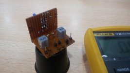
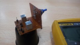
Try to upload photo again - always rotated when I post from my phone.
What are the values of those resistors on the caps? On first look they seem a bit small (in wattage).
FYI - the Elektor Crescendo amp from 1982 I think did specify dual rectifiers - one per rail. There was no guidance or rationale given. Mind you I don't think the PS was the main concern then at Elektor and certainly not now.
Pops.
In the Q-Watt Elektor article is does state the following: -
"The PCB is specifically designed for use as a monaural amplifier (monoblock). For a stereo amplifier you can simply build two of the boards and mount them in an enclosure together with the power supply. You should preferably use two separate power supplies (one for each channel)."
The Q-Watt Measured Performance also states:-
"(Measured with a power supply consisting of a 500 VA power transformer with two 40 V secondaries (Nuvotem type 0500P1-2-040) and four external 10,000 μF, 100 V buffer capacitors)"
And in the parts list it gives us this: -
"Power Supply (for one amplifier) Power transformer: sec. 2x40V, 500VA (e.g. Nuvotem 0500P1-2-040 for 230 VAC mains) Bridge rectifier: 200V, 35A (e.g. GBPC3502) (Fairchild) Four 10,000μF, 100V electrolytic capacitors (2 in parallel on each supply rail)"
What are the values of those resistors on the caps? On first look they seem a bit small (in wattage).
Hey Delange. Am using 0.5W resistors, 13kR. Actual dissipation is about 233 mW each when feeding from 55V.
Haven't figured out final location for bleeders yet.
Pops.
- Home
- Amplifiers
- Chip Amps
- My Q-Watt project