I plugged my nose, closed my eyes and jumped off the edge into the cold, deep, scary water. I found what appears to be a good-shape Pilot 602 Receiver. Everything appears to work except getting no sound from AM. It appears to be fairly well cared-for. Knobs are original and cosmetic condition is good. Has been dusted but needs more thorough cleaning. Does not appear to have been molested. All solder joints look the same. Sounds good.
It prolly needs "caps," (I'll understand their function better after I've done some reading). Has at least one Telefunken tube, but I have not opened the box yet. I have seen pictures. I will take pictures and post them, of course.
I would like to clean this thing up a bit, and I assume it's okay to spray alcohol onto the wires while it's plugged in. Kidding. I am interested in learning what solvents and procedures are recommended. I do not want to wipe off any of the lettering. Also.....knowing little about electronics, I wonder if there are any components that might store electricity. In other words, even if this thing has been unplugged for a time, I wonder if there are any components I will need to "discharge" before it's safe.
Oh.......I paid $150. I think I did well. Did I?
The caps (capacitors) can hold a charge for a while,You'll want to check them with a DMM/voltmeter to be sure that it's safe to poke around inside. Also,if the caps are original they are old enough to need to be replaced.
Do some more reading before you go poking around,It can be dangerous,but if you're careful it should be fine.
Here's a thread I found really quick on Google about re-capping one of these..
Recapping a Pilot 602. A love story. Really. - AudioKarma.org Home Audio Stereo Discussion Forums
Also,I suggest reading through the high voltage safety thread here:
http://www.diyaudio.com/forums/tubes-valves/30172-safety-practices-general-ultra-high-voltage.html
Thank you, DJ.
It sounds like a light bulb can be used to discharge caps. I assume this is as simple as a light bulb socket with one of the two wires connected to ground, and the other placed on a cap's conductor. The light bulb will light, then dim. Is this correct?
Also, I would like information about cleaning amplifiers. After de-energizing the unit and caps, I imagine I can spray something that will loosen dirt and dust and crud, then evaporate. WD-40 leaves residue, but it looks like people use it to clean pots and such. And finally.....the chassis of this amp has printing on it, to identify which tubes go where, and other information. I do not want to dissolve or damage this printing. Suggestions?
Something must be wrong. I'm asking DIY questions on what I thought was a DIY site and getting no advice. Well, that's not exactly true. I'm getting questions about whether I understand that lethal voltages are present in these systems, and being told to study up on safety practices and electrical circuitry. Yes, I understand about high voltage dangers. Yes, I have read through the eighteen-page safety thread. I have read various treatises on electrical circuitry. I have looked at "Valve Amplifiers" by Morgan Jones and perhaps one day I will join you guys in your esoteric discussions of the pluses and minuses of this or that circuit design. But for now, I think I have been crystal clear in my current objective. I am primarily looking for a sonic outcome. I now have an amplifier that would likely make a decent first project. It has old, tired caps and prolly some tired tubes and whatnot. I am taking this one step at a time and yes, I intend to be careful. That's why I am asking these questions.
I will go looking for literature on de-energizing caps. In fact, given sufficient time, I suppose I could do this entire project without coming here and asking you guys to provide any information. But I just thought that this project of mine is a DIY project and that this was a DIY site. And I think I am fairly intelligent and resourceful. I wish I had someone's answer to my question about cleaning solvents. I know for a fact that WD-40 leave considerable residue, but it sounds as if people use it to clean electronics anyway. True? I also hear of another product.....DeOxit? Does anyone use vinegar? What precautions should I take to protect against damaging the screen-print information printed right on the chassis?
Perhaps my questions are too basic. Too simple. Uninteresting. Okay. Does this mean that newbies are on their own until they get some experience under their belt? Judging by the warnings and cautions I'm getting, it would NOT be good for a newbie to launch into a project without some guidance.
I will continue looking for answers in literature. Advice would be helpful and welcome.
Hello! Welcome!
Don't get mad at the answers you are getting/not getting - sometimes things happen slowly here...
You want specific advice, here is some - -
De-energizing:
Unplug the unit and wait 10 min. That should be enough to get everything dead. Obviously don't plug it in while cleaning or working on it.
Cleaning:
WD-40 and audio components should never meet. Get some 'tuner cleaner' or 'electronics cleaner' from Radio Shack and just use that in the potentiometers. (The small cans with 3 wires on them that connect to the shaft of the various knobs. Sometimes they are stacked. Clean all of them.)
Don't clean the tuner gang (the big comb-looking turny thing that has the string attached to it) until you do some research on how to properly clean it.
Chassis top, front and outside - Get a toothbrush, q-tips, some clean rags and water. A little isopropyl alcohol mixed in the water will help it evaporate better. Carefully remove all your tubes. Make your cleaning tools damp and go slowly. Take your time. This will help keep your silkscreening intact. There is no spray that is appropriate for this that I am aware of.
Circuit rejuvenation - I am going to assume that you are not going to change much of the circuit, but instead just get it working like it was new. (A good idea, these are good sounding units!)
'Caps' are capacitors, which in your unit look like;
- Big silver cylindrical cans sticking up near the transformers.
- Brownish 'tootsie-rolls' with leads out of both ends and names like sprague and markings that have 'uf' 'nf' or 'pf'
- Lighter brown discs
- possibly some brown red or black boxes with colored dots on them.
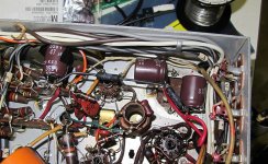
Time to steal some photos and point this out -
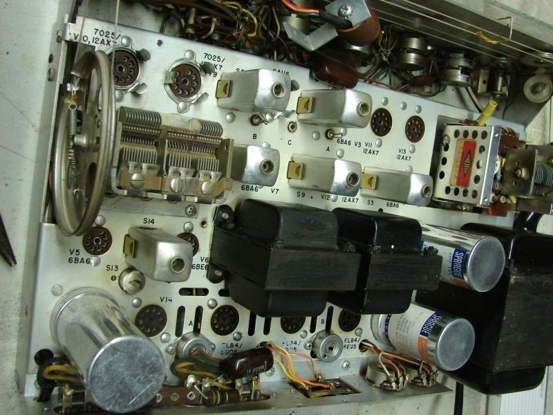
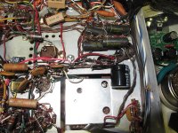
See the big cans by the transformers that say Sprague? (and the one in the lower left...) Figure out what they say on the side and post it here, someone will help you find the replacements.
Also in this photo, do you see the row of dual round things in the upper right? behind where the knobs would be? Those are the pots that need cleaning with the stuff from radioshack. Spray a little in there and move the knob back and forth a bunch.
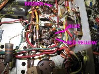
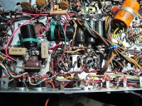
There is no doubt that all the big cans must be replaced. They are too old to be working properly anymore. There are also some paper ones under the chassis that are also shot. (it's a function of age) like the one on the left in this photo -
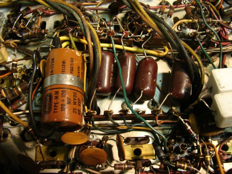
The row of 4 darker ones next to it should also be replaced. Those are most likely the output tube coupling caps.
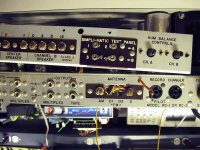
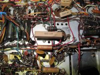
You also have another problem - the Selenium rectifiers. These guys:
They also age themselves to death and need to be replaced. The problem is that there is no direct replacement and you will need to add a resistor after the bridge to get your supply voltages correct.
As you are cleaning this, you will have your tubes removed... Fond somewhere in your town that has a tube tester and check all your tubes. Some might be weak or dead.
Lastly, and this should be first, get a schematic! A quick google didn't come up with one, so you might need to dig a bit. Perhaps ask this guy - tbavis(at)rochester(dot)rr(dot)com.
Don't get mad at the answers you are getting/not getting - sometimes things happen slowly here...
You want specific advice, here is some - -
De-energizing:
Unplug the unit and wait 10 min. That should be enough to get everything dead. Obviously don't plug it in while cleaning or working on it.
Cleaning:
WD-40 and audio components should never meet. Get some 'tuner cleaner' or 'electronics cleaner' from Radio Shack and just use that in the potentiometers. (The small cans with 3 wires on them that connect to the shaft of the various knobs. Sometimes they are stacked. Clean all of them.)
Don't clean the tuner gang (the big comb-looking turny thing that has the string attached to it) until you do some research on how to properly clean it.
Chassis top, front and outside - Get a toothbrush, q-tips, some clean rags and water. A little isopropyl alcohol mixed in the water will help it evaporate better. Carefully remove all your tubes. Make your cleaning tools damp and go slowly. Take your time. This will help keep your silkscreening intact. There is no spray that is appropriate for this that I am aware of.
Circuit rejuvenation - I am going to assume that you are not going to change much of the circuit, but instead just get it working like it was new. (A good idea, these are good sounding units!)
'Caps' are capacitors, which in your unit look like;
- Big silver cylindrical cans sticking up near the transformers.
- Brownish 'tootsie-rolls' with leads out of both ends and names like sprague and markings that have 'uf' 'nf' or 'pf'
- Lighter brown discs
- possibly some brown red or black boxes with colored dots on them.
Time to steal some photos and point this out -
See the big cans by the transformers that say Sprague? (and the one in the lower left...) Figure out what they say on the side and post it here, someone will help you find the replacements.
Also in this photo, do you see the row of dual round things in the upper right? behind where the knobs would be? Those are the pots that need cleaning with the stuff from radioshack. Spray a little in there and move the knob back and forth a bunch.
There is no doubt that all the big cans must be replaced. They are too old to be working properly anymore. There are also some paper ones under the chassis that are also shot. (it's a function of age) like the one on the left in this photo -
The row of 4 darker ones next to it should also be replaced. Those are most likely the output tube coupling caps.
You also have another problem - the Selenium rectifiers. These guys:
They also age themselves to death and need to be replaced. The problem is that there is no direct replacement and you will need to add a resistor after the bridge to get your supply voltages correct.
As you are cleaning this, you will have your tubes removed... Fond somewhere in your town that has a tube tester and check all your tubes. Some might be weak or dead.
Lastly, and this should be first, get a schematic! A quick google didn't come up with one, so you might need to dig a bit. Perhaps ask this guy - tbavis(at)rochester(dot)rr(dot)com.
Last edited:
There is a huge amount of information available on this website from previous posts. If you use the search feature (I like the "advanced search", myself), you will probably find most of the answers to your questions, and to questions that will arise. Here's an example---
http://www.diyaudio.com/forums/construction-tips/178215-discharging-those-big-old-capacitors.html
When I clean-up an older unit, I rely mostly on q-tips soaked in a cleaner such as Lysol or something similar that can be found at the grocery store. I like the "Brillo" brand, but it can be hard to find. Always test the cleaner in an inconspicuous area to be certain that it will not leave a stain or remove lettering. Rinse the reside from the cleaner with a q-tip and water and rubbing alcohol, and be certain that it is completely dry before plugging it in. I tend to shy away from doing extensive cleaning in the RF sections, since these can be sensitive areas, particularly high frequency components found in some older "FM" front ends. Sometimes there are small inductors and even stub wire capacitors that are tuned by bending the component. Disturbing these can knock things "out of whack".
Wow! This is just EXACTLY what I needed. Art and 6L6, thank you very much for taking the time. Immensely helpful, especially the details in your advice.
I have sent an email to the guy who asked "tbavis(at)rochester(dot)rr(dot)com" for the schematic, but just not the requestee. I'll do that now.
Again, thanks. Very helpful. I hope my post did not sound too exasperated. I'm a joyful guy. Really. Impatient at times, but blessed with a joyful outlook.
Did I mention my gratitude? Thanks again.
I've begun the photojournalism thing. Haven't figured out how to take the bottom off yet.
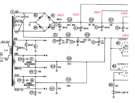
I scored a schematic, but it's in several one-page .jpg files. The good news is that it includes a four pages of parts and their specifications.
I've got another question. How does one clean tube sockets. Some of these tube pins are pretty small......WAY too small for pipe cleaners. And.....would I use vinegar. Vinegar is what I use to remove corrosion, but I'm just a car guy.
Judging by the warnings and cautions I'm getting, it would NOT be good for a newbie to launch into a project without some guidance.
Which is exactly why I posted the warning/info on the High Voltages involved.We don't know your level of experience,so the best bet is to start from the beginning. -It's with the best of intentions in mind. (We don't want to see anyone get killed from poking around in something they don't understand.)
Sometimes threads get lost,or we take a bit to get back to you (It's what,a week later,and I'm just now seeing this thread again?) But we will generally at least point you in the right direction.
")
Cleaning tube sockets can be kind of tricky. I usually use DeOxit for cleaning contacts/sockets/pots,it works well. Spray a very little bit (it doesn't take much) in the socket pins,and work a tube in/out a couple times..for octal sockets I've used Q-tips with the cotton pulled off the end,so it's just the paper 'stick'..spray some DeOxit on there,and work it down in the socket pins a couple times.
Also,like ArtG says,hit up the search function if you're feeling antsy,there's LOADS of info on here,the trick is to find it!
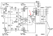
Interesting find, the center tap of the output transformers are wired to the screen grid pin of the 6BQ5's. This means that the screen potential might even be higher than the anode. Apparently, someone forgot to tell the soldering mavens that the red-yellow wire was to be connected to the junction of the 100R/40uF capacitor.
Diodes replaced with UF4007, so will pick up ~4V.
All the can electrolytics are shot, so replaced with new.
100R 10W resistor replaced with a Caddock affixed to the chassis -- this will remove some of the heat from the under-compartment.
Diodes replaced with UF4007, so will pick up ~4V.
All the can electrolytics are shot, so replaced with new.
100R 10W resistor replaced with a Caddock affixed to the chassis -- this will remove some of the heat from the under-compartment.
Attachments
> the screen potential might even be higher than the anode.
This is Not A Problem.
Not a big problem, but it in simulation it worsens THD by ~2.4dB.
Will have to measure. Just jumper the 100R resistor.
First tests -- had to replace one of the ECC83's, the bypass caps from the phase splitter were replaced with 0.1u/630V Panasonic polypropylenes as the old film caps were leaky. One of the DC balance pots was completely shot and replaced with a spare CTS unit found in the junk box.
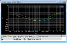
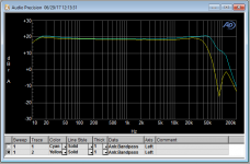
1W, 1kHz THD 0.1%
I think that the 100uF cathode bypass cap has to go...
1W, 1kHz THD 0.1%
I think that the 100uF cathode bypass cap has to go...
- Status
- This old topic is closed. If you want to reopen this topic, contact a moderator using the "Report Post" button.
- Home
- Amplifiers
- Tubes / Valves
- My Project: Pilot 602