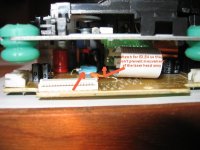
Here the side view of the modified PCB. It is rather easy to do.
One thing to take care is when replacing E3,E4 caps, make sure that the new ones to get in the way of the laser head assembly when it slides. Make sure to install these two caps as close to E2 as possible, incline them a little bit is possible.
I used blue tack to fix the new crystal and keep it from vibrating.
Attachments
Hello Algar
I´m also appreciating your progress, thanks. Very helpful. Some doubts came up too. I noticed you (and all others) keep the white flat cable socket in the main PCB. What about the other end, in the display board? I supose you´re going to solder single wires to the socket pins and then to the separete push buttons and the LCD screen.
Thanks for comments.
BTW I didn´t touch my kit so far because I´waiting for PS parts, where I´ll start on.
Ha, Ha! You're going ahead of me JC Fardo, I was getting there ")
I'm planning to replace this white flat ribbon cable because it is not long enough for my case. Also it is cumbersome to route and fragile.
Also, I want to be able to just unplug the top transport section with its metal base, and remove it from the butcher block wood base.
My plan is to use small 30 awg wirewrap wires and solder them directly at the connector pins, then break these wires using a DB25 connector female. This connector will hang down from the top metal transport and connect on the male DB25 mounted on the wood base.
The other wires TOC switch, +/-V supply and display Led supply will be routed through a DB9. Only the digital output signal will be routed using a small coax cable.
I'll try to balance the top metal platform by routing the the DB25 on one side of the transport, and the DB9 on the other side.
To remove the transport, I will only need to unsolder the coax, then unplug both DB connectors from the wood base.
Voilà, answer to your question
Not there yet. I'm stuck into an hotel room and I can only verify that every functions is working, so the two PCB I modified are still working. This proof that Peter Daniel modifications instructions are perfect. I didn't have to use any cap on the new crystal. I just modified the transport PCB according to the instructions and it worked.
I don't have any DAC with me to connect it to. Also, I can just compare it to an other transport, certainly not to the original EZ31B, that sounds just plain awfull (well it was just a cheap boombox anyway).
I don't have any DAC with me to connect it to. Also, I can just compare it to an other transport, certainly not to the original EZ31B, that sounds just plain awfull (well it was just a cheap boombox anyway).
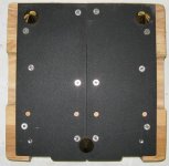
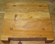
Here the wood platform undergoing finishing. You can see the DB25 connectors cut-out on the top, on the left. I can use only one DB25, the LCD need only 18 wires, +/-V and TOC switch and this is all I need. The small hole close to it, is for the SPDIF coax cable.
Into the base, I dig an other compartment to receive a Tent Audio XO2 Clock, if I decide to try one.
Into the base, I dig an other compartment to receive a Tent Audio XO2 Clock, if I decide to try one.
Attachments
Interest Check
For all of you whose interested in the platter and screw on cap for the shigaclone mechanism, I am able to supply. The cost is USD$50 including postage to any where in the world. it will be made either in delrin or nylon. Pictures to follow soon. PM me, from Singapore.
For all of you whose interested in the platter and screw on cap for the shigaclone mechanism, I am able to supply. The cost is USD$50 including postage to any where in the world. it will be made either in delrin or nylon. Pictures to follow soon. PM me, from Singapore.
Algar_emi said:Here the wood platform undergoing finishing. You can see the DB25 connectors cut-out on the top, on the left. I can use only one DB25, the LCD need only 18 wires, +/-V and TOC switch and this is all I need. The small hole close to it, is for the SPDIF coax cable.
Into the base, I dig an other compartment to receive a Tent Audio XO2 Clock, if I decide to try one.
Any progress on this one??!
Protecion fuse?
Hello Sylvain
Did you use any fuse?. My clone is just about to get finished. I had only weekends to work and a lot of mess happened with boxes, frames, etc.
How is your progress
Thanks and best regards
JC
Algar_emi said:And the rear power supply view.
Hello Sylvain
Did you use any fuse?. My clone is just about to get finished. I had only weekends to work and a lot of mess happened with boxes, frames, etc.
How is your progress
Thanks and best regards
JC
- Status
- This old topic is closed. If you want to reopen this topic, contact a moderator using the "Report Post" button.
- Home
- Source & Line
- Digital Source
- My own ShigaClone CD Transport Version