latest layout
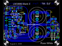
As promised, I have tweaked the layout (its amazing what you notice when you actually build a PCB) and increased the size of a few components, mostly to accomodate slightly larger film caps for the Zobel and AC in, and give you a little more clearance in certain spots, plus I wanted to allow the use of a vertically mounted zobel resistor since I have some 5W jobs that are huge.") You could still use a smaller resistor there without issue.
You could still use a smaller resistor there without issue.
Cheers!
PDFs of copper and component layers to come.
As promised, I have tweaked the layout (its amazing what you notice when you actually build a PCB) and increased the size of a few components, mostly to accomodate slightly larger film caps for the Zobel and AC in, and give you a little more clearance in certain spots, plus I wanted to allow the use of a vertically mounted zobel resistor since I have some 5W jobs that are huge.
You could still use a smaller resistor there without issue.Cheers!
PDFs of copper and component layers to come.
Attachments
Good question, as long as you use good bypass caps(the 220uf and 100nf on my board) your highs will not suffer in the least. I have done extensive testing with all sorts of snubber arrangements (my own and Carlos') and found the scheme I have chosen here to be quite ideal. I can assure you there is no lack of nice airy and detailed highs, as I am listening right now to the nutcracker suite, and the bells and picolos sound great!  The bass is also very tight, not loose or out of control at all. Low ESR caps are critical here. I used panasonic FCs for the electrolytics.
You have to take a lot of what you get out of DIY audio from experience. I have built dozens of amps and dozens more PSs and experimented with them all. You will not be disapointed.
Cheers!
Russ
The bass is also very tight, not loose or out of control at all. Low ESR caps are critical here. I used panasonic FCs for the electrolytics.You have to take a lot of what you get out of DIY audio from experience. I have built dozens of amps and dozens more PSs and experimented with them all. You will not be disapointed.
Cheers!
Russ
So your saying you prefer your simple bypass cap solution vs carlos' cap+R solution? Can you give any insight on how they compare?
and it also boggles my mind how no one in all this time has tried simple bypass caps. everyone's been using low capacitance until the snubber came along...
and it also boggles my mind how no one in all this time has tried simple bypass caps
. everyone's been using low capacitance until the snubber came along...homer09 said:So your saying you prefer your simple bypass cap solution vs carlos' cap+R solution? Can you give any insight on how they compare?
and it also boggles my mind how no one in all this time has tried simple bypass caps
Yes, I prefer the scheme I have chosen over any snubber solution. The design choice it quite intentional and deliberate and born out of hours of research and testing, and many a lunch hour at the UT lab.

I have a lot of respect for all the work that went into Carlos' snubber design, but my ears and the scope see no benefit in it to recommend it over what I have here.
Now be sure you keep this in mind. I design for myself, and what I know is good "for me". I love the sound of this amp, it is controlled and transparent. I am sure Carlos and other love theirs just as well.
One of the nice things about designing your own work, is you have every prerogative so utilize what you trust, and what you know from experience.
Cheers!
Russ
I thought about bleader resistors (and have them on some of my other amps), but I prefer to omit them as I do not like the constant current draw. it would be simple add one (or two) yourself, just drill a couple holes in the rails. Or solder them to the leads of the caps.
As for my impressions of the snubber, it is not that it introduces anything negative, but it is different, just not better in my opinion. Most of the benefit of the snubbered PSU in my experience is simply the better bypassing. I have kept the bypassing, as that does make a huge improvement both in sound and in stability.
Cheers!
Russ
homer09 said:So your saying you prefer your simple bypass cap solution vs carlos' cap+R solution? Can you give any insight on how they compare?
and it also boggles my mind how no one in all this time has tried simple bypass caps everyone's been using low capacitance until the snubber came along...
How does it boggle ? -- all of National Semi's ap-notes have simple bypass recommendations.
Carlos seems to think that 1R in series with 100nF reduces the supply impedance -- it doesn't have any material effect as far as I have been able to determine either in theory or by empirical method.
Try this -- if you have a spectrum analyzer -- (a real spectrum analyzer, not a sound card which goes to 20kHz) -- use an RF sniffer to ferret out the radio frequency interference coming from the diode bridge.
jackinnj said:Try this -- if you have a spectrum analyzer -- (a real spectrum analyzer, not a sound card which goes to 20kHz) -- use an RF sniffer to ferret out the radio frequency interference coming from the diode bridge.
Do you think I have not already tested that?
I am here at the physics lab at UT (I work here from time to time) and I have the use of GHz range equipment. This design has no more interferance from the bridge(in fact less, the caps make great RF/EMI shields) as my designs with seperate PS.
Mind you, I am a noob when it comes to this test equipment, but my budddies are not. They have scrutinized the design very much.
Cheers!
Russ
B.I.G said:great layout
Please do, let me know if you need any help. I would like to get an independant unbiased opinion on the layout as well as the sound.
Cheers!
Russ
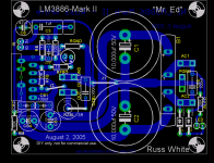
Did some renderings of a Mr.Ed version I was thinking about trying.
http://www.ettnet.se/~tobias/diy/mr_ed/
99% copy of Russ's but with his permission
Just changed the rectifiers for eight MUR860 with caps parallell to 'em.
Cheers
http://www.ettnet.se/~tobias/diy/mr_ed/
99% copy of Russ's
but with his permission Just changed the rectifiers for eight MUR860 with caps parallell to 'em.
Cheers
Russ White said:As for my impressions of the snubber, it is not that it introduces anything negative, but it is different, just not better in my opinion. Most of the benefit of the snubbered PSU in my experience is simply the better bypassing. I have kept the bypassing, as that does make a huge improvement both in sound and in stability.
Don't mix things, the 'better bypassing' is just what I have always used (and recommend) with op-amps.
That's one thing.
The snubber allows you to use as big caps as you want on the PSU, without side effects. And I mean integrated on one PCB or separated.
As I have been reporting lately, the 1R+100nf values were initial values, and I am using now much different ones, with great results.
carlosfm said:
Don't mix things, the 'better bypassing' is just what I have always used (and recommend) with op-amps.
That's one thing.
The snubber allows you to use as big caps as you want on the PSU, without side effects. And I mean integrated on one PCB or separated.
As I have been reporting lately, the 1R+100nf values were initial values, and I am using now much different ones, with great results.
Carlos,
I am not mixing things. I just found that is that good bypassing sounds (and measures) better without the snubbers and the configuration I have chosen.
I am sure you like your snubber values, and I do to, I just like this better. If you share how you calculate your values, I will try them, and I will give my honest view. Until then, I think anyone who actually trys this circuit will love it, no matter how much you protest about he lack of snubbage. Cheers!
Russ
tobias_svensk said:Did some renderings of a Mr.Ed version I was thinking about trying.
http://www.ettnet.se/~tobias/diy/mr_ed/
99% copy of Russ's
Just changed the rectifiers for eight MUR860 with caps parallell to 'em.
Cheers
Tobias, you know I love it!!! Its a great 2 sided design, and a super candidate for a professional PCB. Great work, and thanks as always for your input and help.
You help make this fun for me. Cheers!
Russ
- Status
- This old topic is closed. If you want to reopen this topic, contact a moderator using the "Report Post" button.
- Home
- Amplifiers
- Chip Amps
- My NI chipamp Mark-II - Mr. Ed :)