Algar_emi,
Sorry for the stupid/newb questions... but...
In the post #15 you spoke about 'coupling caps', and now it's about 'bypass' ones! Aren't these the same caps, I mean C2 in the original schematic?
If I read well the post #15 this wima caps is not supposed to sound great (?). Are you still using it in your amplifier?
Thanks!
Hi All,
I've had a few emails, so I figure that I'd add a little more.
The attached pic shows how I laid out components and the boards within the Par-Metal chassis. I don't have any numbers on the heatsinks since I got them at a local surplus house (which has a lot more if you are in the Bay Area, CA at all), in untouched form. I measured the temps yesterday and they run at about 105 degrees F (heatsink temp, not junction or case temp) without the case lid on. This doesn't seem too excessive, so I presume they are adequately heatsinked. I am currently running the bias current at its max: about 255mA.
Bryan
Attachments
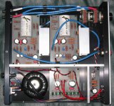
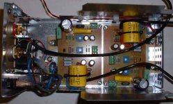
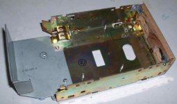
My amp is completed. As described before it is done with two main assemblies. The bottom section contains the case main frame, the two amp PCB's , the AC EMI filter and power switch + Blue led, the rear panel and the rear equalizer DIP SW.
Here an image of the bottom section.
Here an image of the bottom section.
Attachments
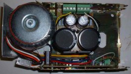
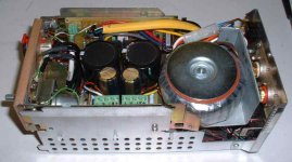
On top of that is the power supply assembly. It contains the transformer, supply and equalizer PCB's. A steel plate insulate the transfo from the input RCA connectors. There is no induce 60Hz noise in the amp from the transfo. All audio signal cables are also shielded.
I mounted the amp pcb on the bottom because I wanted to mount the two power FET's on the case bottom plate for maximum heat transfer.
The wiring is done in such a way that I can rotate the top section and have access to the bottom map PCB and do testing and adjustements on them.
I mounted the amp pcb on the bottom because I wanted to mount the two power FET's on the case bottom plate for maximum heat transfer.
The wiring is done in such a way that I can rotate the top section and have access to the bottom map PCB and do testing and adjustements on them.
Attachments
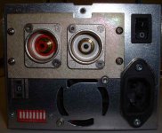
And finally a view of the rear panel with two nice Neutrik RCA Connectors abd the remote DIP SW of the sound equalizer easily accesible from the back.
The fan is still mounted on the case. I may use it because the amp is getting quite hot on the bottom. If I connect the fan, I`ll make sure it will run at minimum speed. I won't hear it with headphones anyway...
The fan is still mounted on the case. I may use it because the amp is getting quite hot on the bottom. If I connect the fan, I`ll make sure it will run at minimum speed. I won't hear it with headphones anyway...
Attachments
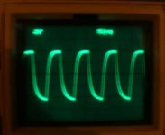
Here a bad image of a 10Khz square wave showing the typical ZEN response. Since the amp bandwidth is only 20Khz (-3dB), a lot of the 10Khz square waves harmonics are already attenuated and cause the waveform round corner. The sound is still very good indeed, so why bother with a square wave not perfect ")
Here some final measurements of my amp:
All measurements done in 33 ohms resistors simulated headphone load, both channels loaded.
Bandwitdth (-3dB, ref 1V, 1Khz): 5Hz to 20Khz
Channels Difference: <0.05dB (Good FET matching I guest)
Crosstalk: -60dB (1Khz), -42dB (10Khz)
Here some final measurements of my amp:
All measurements done in 33 ohms resistors simulated headphone load, both channels loaded.
Bandwitdth (-3dB, ref 1V, 1Khz): 5Hz to 20Khz
Channels Difference: <0.05dB (Good FET matching I guest)
Crosstalk: -60dB (1Khz), -42dB (10Khz)
Attachments
After using it for some time now I did some mods.
-Disconnected the Equalizer. I didn't find it usefull for me and it even change the sound for the worst. It makes also my amp interior cleaner. I have to agree thought, that if someone is using it with the DIP switch mounted directly to the pcb, the result could be better than what I experienced. My DIP switch was mounted on the amp's back and there was all the switch wires running inside the amp.
-I connected the cooling fan that was already mounted on my case. It is supplied directly from J5 (Led Supply) on the power supply. With my fan the dropout resistors R1-R2 provide just enough voltage (6V) to run at low speed (and low noise) the small 12V fan.
-Drilled ventilation holes in the transformer mounting plate, so the top section will be ventilated by the fan too.
Now the amp runs just warmer , before it was on the toasted side
  and I was not that comfortable with that.
It is now a better amp.
-Disconnected the Equalizer. I didn't find it usefull for me and it even change the sound for the worst. It makes also my amp interior cleaner. I have to agree thought, that if someone is using it with the DIP switch mounted directly to the pcb, the result could be better than what I experienced. My DIP switch was mounted on the amp's back and there was all the switch wires running inside the amp.
-I connected the cooling fan that was already mounted on my case. It is supplied directly from J5 (Led Supply) on the power supply. With my fan the dropout resistors R1-R2 provide just enough voltage (6V) to run at low speed (and low noise) the small 12V fan.
-Drilled ventilation holes in the transformer mounting plate, so the top section will be ventilated by the fan too.
Now the amp runs just warmer
, before it was on the toasted side and I was not that comfortable with that.It is now a better amp
.I finally manage to get a CLIO measuring system in my workshop. Using that I was able to do better measurements of my ZEN amp.
At normal listening level: Vout = 20mv at 1K in 33 ohms resistor
Harmonic (THD) and Intermodulation (IMD) distorsions are:
IMD(%) IMD(%)
1Khz 0.06 0.06
10Khz 0.02 0.04
Very good results, much better than the 0.3% THD that I was measuring using my old HP334, that seems defective...
in 33 ohms, 1% distorsion occurs at 0.57V, almost full volume...
At normal listening level: Vout = 20mv at 1K in 33 ohms resistor
Harmonic (THD) and Intermodulation (IMD) distorsions are:
IMD(%) IMD(%)
1Khz 0.06 0.06
10Khz 0.02 0.04
Very good results
, much better than the 0.3% THD that I was measuring using my old HP334, that seems defective...in 33 ohms, 1% distorsion occurs at 0.57V, almost full volume...
Hello Algar,
0.3% @ 20mVrms @ 1KHz is definitely too much, maybe your D.A. is a bit noisy or its noise floor is such that this limits the dynamic with such low levels.
At 50mVrms (the lowest level for my HP8903B to work as distortion analyzer) I read 0.05% THD+N, 400HP and 30KHz LP filters on.
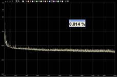
With my Clio, when the 20mVrms output level is setted, the THD percentage is about 0.014%, but I can see the only 2nd harmonic over than 80dB below.
Anyway, the differences does not seem so dramatic to me.
Best regards
Marcello
0.3% @ 20mVrms @ 1KHz is definitely too much, maybe your D.A. is a bit noisy or its noise floor is such that this limits the dynamic with such low levels.
At 50mVrms (the lowest level for my HP8903B to work as distortion analyzer) I read 0.05% THD+N, 400HP and 30KHz LP filters on.
With my Clio, when the 20mVrms output level is setted, the THD percentage is about 0.014%, but I can see the only 2nd harmonic over than 80dB below.
Anyway, the differences does not seem so dramatic to me.
Best regards
Marcello
Attachments
Power consumption
Hi Phoneamp experts,
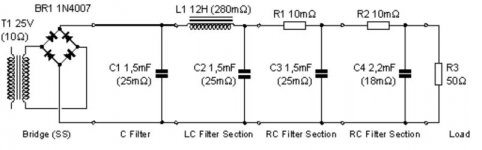
I am now building up the powersupply for my Tortello / Digi headphone amp, and I would like to know your etimate as to how much watt the amp will consume when biasing on 200 mA.
I intend to built the following PSU: See attached picture.
The values for R1 an R2 depend of course on the load of the amp.
This setup would give a ripple of appr. 0,000025 Volt
Thanks for any info!
Lucas
Hi Phoneamp experts,
I am now building up the powersupply for my Tortello / Digi headphone amp, and I would like to know your etimate as to how much watt the amp will consume when biasing on 200 mA.
I intend to built the following PSU: See attached picture.
The values for R1 an R2 depend of course on the load of the amp.
This setup would give a ripple of appr. 0,000025 Volt
Thanks for any info!
Lucas
Attachments
Hi Tortello. I just installed my new Clio 7.02 with the external measuring box. I confirmed that the correct distorsion reading is 0.3% at 600mV output, 0.707V input, 1Khz in 33 ohms (about the Grado impedance).
However, at 100mv out, I also have 0.05% Is this normal?
Any information to guide me on how to reduce the distorsion?
Thanks...
However, at 100mv out, I also have 0.05% Is this normal?
Any information to guide me on how to reduce the distorsion?
Thanks...
Algar_EMI,
I stumbled on it just now. This is a very interesting project and a nice job. I would love to try building one. One question I have is, how does this amp compare with any other headphone amps, commercial or DIY? Would anybody else who has built this be able to answer this question?
I have a PPA with Glassman Diamond suffers as well as a Millett Hybrid and was wondering if this would out do any of those.
Thanks for sharing your project with us,
Regards,
Dinesh
Hi Dinesh,
Have you checked out Tortello's write up of
the design on headwize.com?
http://headwize.com/projects/showfile.php?file=pellerano_prj.htm
Cheers,
Dennis
Have you checked out Tortello's write up of
the design on headwize.com?
http://headwize.com/projects/showfile.php?file=pellerano_prj.htm
Cheers,
Dennis
- Status
- This old topic is closed. If you want to reopen this topic, contact a moderator using the "Report Post" button.
- Home
- Amplifiers
- Pass Labs
- My new ZEN-like headphones amp