Re: "It's just that the bases need to be bias'ed around ground."
Can be done by applying a small current from the Supply Rails with CCS's to the Emitters of Q10+11 and Q18+19 respectively, whilst retaining R14+15 (different value).
Long time since I was involved with this type of Circuit topology!
Anyway, isn't there a noise trade-off with the FET inputs?
Usually Power Amplifiers are driven from a Low Impedance Source.
Just some thoughts
Mik
I was under the impression that the 2SK170s were coveted low noise input transistors. They're obsolete though. What I like about them is the relatively high Idss of 10mA, which makes for a rather strong input stage. At least in simulation, I've tried a bunch of different devices, but none come close in THD performance to the 2SK170's.
I haven't tried 550C as input devices running on 10mA, only on 2.5mA. The IPS current may actually be the main contributor to THD reduction.
One thing is for sure, the performance is a great deal worse without the input stage. It's not intended to be driven directly by an input signal, but the control (error) signal instead.
As for input impedances, I wanted to give an eventual amp a line impedance of 47K, buffered by a unity gain opamp. An opamp will drive the IPS input as it is rather low ohmic to mitigate noise and lessen the impact of the feeback input pole. This way I can be flexible about the feedback network impedance")
I think I want to stick to JFETs as IPS input devices, but I don't really know what would be modern, good substitutes for SK170s.
I haven't tried 550C as input devices running on 10mA, only on 2.5mA. The IPS current may actually be the main contributor to THD reduction.
One thing is for sure, the performance is a great deal worse without the input stage. It's not intended to be driven directly by an input signal, but the control (error) signal instead.
As for input impedances, I wanted to give an eventual amp a line impedance of 47K, buffered by a unity gain opamp. An opamp will drive the IPS input as it is rather low ohmic to mitigate noise and lessen the impact of the feeback input pole. This way I can be flexible about the feedback network impedance
I think I want to stick to JFETs as IPS input devices, but I don't really know what would be modern, good substitutes for SK170s.
Philips BF862
and BF862 from Philips.
Maybe still better !
http://www.nxp.com/documents/data_sheet/BF862.pdf
and BF862 from Philips.
Maybe still better !
http://www.nxp.com/documents/data_sheet/BF862.pdf
Thanks! I'll have tro try those, though I don't have models for them. For simming purposes I've settled on BC550 now, I found the IPS to optimally work with them running an LTP current of 5mA.
This has a side benefit that the IPS shunt currents when overdriven remain small too, no more than the LTP can provide.
For this next iteration I applied another benefit of this topology which was not obvious from the previous schematics; which is that the IPS and the VAS front-end can run on its own low power supply.
The only reason the VAS supplies are relatively high, is to facilitate the desired output swing. Other than that, the high supply is not needed at all. One would cope with this in the IPS by using high Vceo transistors, or put zeners in the rails to provide voltage drop / power dissipation.
Eventhough the IPS supply was reduced to +15/-15V the performance remains the same. Especially because I progammed the IPS output to sit 'halfway' the available output swing (7.5V).
I've also redone the layout a bit in such way that the VAS input is a bit better to discern and pull apart. One can now clearly see that what compromises the VAS actually consists of two parts. The first part takes a voltage and converts it to a differential complementary current output (collectors of Q10 and Q17). Then there is the second part, the current mirrors which form the load of the differential current output. So, basically, the VAS as a whole is actually one-and-a-half stage
There's a third modification I made. Now I separated the supplies, I also upped the VAS mirror supplies for a larger output swing. Scaling up the VAS output is easy. Since the VAS front end is a current output I no longer have to be concerned about voltage swing. Therefore I don't need to change anything to the front-end. All one would have to do to increase outputswing range is to raise the VAS supply and increase the zener values of D1 and D11; they cope with the additional voltage and dissipate the associated power so that Q10 and Q17 can be low noise, moderate Vceo types still. Oh and the hawksford cascode bias (R12) needs to be picked such that the cascode bias rail runs about 5mA.
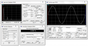
I've actually bested myself as I can now do 250KHz, at this increased output swing and still keep the THD meter at 0.000%
I've also made an 1KHz spectrum plot to show the harmonic content of the circuit. The 2nd and 4th harmonic are gone into the noise floor of -169dB. The 3rd harmonic is still visible at roughly -135dB and the 5th barely visible at -155dB.
I've been able to push the even harmonics to under the noise floor, but I somehow can't make the odd harmonics budge. Overall I think this is stellar performance eventhough it's just a sim, though based on a reallife circuit
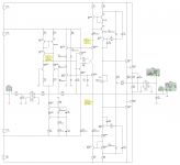
Is the schematic better to view now? It's rather kingsize but now the connecting dots should all be clearly visible.
Edit: Oh, and a little detail, the circuit is loaded by a purely capacitive load of 39uF, it equals a reactance of about 4 ohms with a 1KHz sine output. It's all stable
This has a side benefit that the IPS shunt currents when overdriven remain small too, no more than the LTP can provide.
For this next iteration I applied another benefit of this topology which was not obvious from the previous schematics; which is that the IPS and the VAS front-end can run on its own low power supply.
The only reason the VAS supplies are relatively high, is to facilitate the desired output swing. Other than that, the high supply is not needed at all. One would cope with this in the IPS by using high Vceo transistors, or put zeners in the rails to provide voltage drop / power dissipation.
Eventhough the IPS supply was reduced to +15/-15V the performance remains the same. Especially because I progammed the IPS output to sit 'halfway' the available output swing (7.5V).
I've also redone the layout a bit in such way that the VAS input is a bit better to discern and pull apart. One can now clearly see that what compromises the VAS actually consists of two parts. The first part takes a voltage and converts it to a differential complementary current output (collectors of Q10 and Q17). Then there is the second part, the current mirrors which form the load of the differential current output. So, basically, the VAS as a whole is actually one-and-a-half stage
There's a third modification I made. Now I separated the supplies, I also upped the VAS mirror supplies for a larger output swing. Scaling up the VAS output is easy. Since the VAS front end is a current output I no longer have to be concerned about voltage swing. Therefore I don't need to change anything to the front-end. All one would have to do to increase outputswing range is to raise the VAS supply and increase the zener values of D1 and D11; they cope with the additional voltage and dissipate the associated power so that Q10 and Q17 can be low noise, moderate Vceo types still. Oh and the hawksford cascode bias (R12) needs to be picked such that the cascode bias rail runs about 5mA.
I've actually bested myself as I can now do 250KHz, at this increased output swing and still keep the THD meter at 0.000%
I've also made an 1KHz spectrum plot to show the harmonic content of the circuit. The 2nd and 4th harmonic are gone into the noise floor of -169dB. The 3rd harmonic is still visible at roughly -135dB and the 5th barely visible at -155dB.
I've been able to push the even harmonics to under the noise floor, but I somehow can't make the odd harmonics budge. Overall I think this is stellar performance eventhough it's just a sim, though based on a reallife circuit
Is the schematic better to view now? It's rather kingsize but now the connecting dots should all be clearly visible.
Edit: Oh, and a little detail, the circuit is loaded by a purely capacitive load of 39uF, it equals a reactance of about 4 ohms with a 1KHz sine output. It's all stable
Attachments
Last edited:
How would one apply TPC or TMC to my VAS? I have no loop Cmiller. Well, I sort of do: C3. But since input is not rail referenced, where would I tie to the resistor? Would GND work? Or will I have to introduce a low Z reference for the resistor to connect to? This is the issue I have with TPC. Once would think: Apply a 2nd order filter, but the problem is where the resistor node goes. I even think under classic conditions, the supply rail isn't the right location to tie the resistor to.
I even think under classic conditions, the supply rail isn't the right location to tie the resistor to.
Indeed. In the classic case, the resistor should go to ground, not the rail. See pages 9 to 11 of my paper on two-pole compensation (if reading the whole paper, please be sure to read the addendum, which is the very last page in the PDF after the references):
http://tinyurl.com/TwoPoleCompensation-pdf
Distributed by kind permission of the Audio Engineering Society.
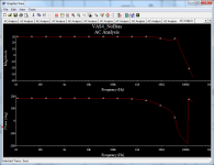
Well, I finally managed to pull an AC plot from the schematic without the sim crashing
It shows a few oddities. Indeed the 'evil' zero at around 50MHz. But the thing that strikes me as odd is that the phase has turned much more than 180 degrees at 0dB gain. Yet the circuit is perfectly stable. I'm thinking the AC analysis doesn't spit out entirely correct data.
I've tried TPC quickly, but then the sim crashes again.
What do you think of the plot?
It shows a few oddities. Indeed the 'evil' zero at around 50MHz. But the thing that strikes me as odd is that the phase has turned much more than 180 degrees at 0dB gain. Yet the circuit is perfectly stable. I'm thinking the AC analysis doesn't spit out entirely correct data.
I've tried TPC quickly, but then the sim crashes again
.What do you think of the plot?
Attachments
When it comes to actually building an amp with it, what powerrating would be most successful for the design to be adopted for building? Once I've designed a final amp around the target power using this VAS, I intend to publish it and make PCBs available once the prototype works and meets my reliability criteria.
I have a hunch that the sonics will be godlike given the consistent performance of the circuit Perfectly flat from over 100KHz! But I won't get to find out until built for which I can't wait.
I have a hunch that the sonics will be godlike given the consistent performance of the circuit
Perfectly flat from over 100KHz! But I won't get to find out until built for which I can't wait.
Last edited:
It shows a few oddities. Indeed the 'evil' zero at around 50MHz.
I'm not sure that's an "evil" zero. Looks like it could be a pole at about 5 MHz followed by a complex pole pair at about 50 MHz.
But the thing that strikes me as odd is that the phase has turned much more than 180 degrees at 0dB gain. Yet the circuit is perfectly stable
This looks to me more like a closed-loop frequency response than a loop-gain frequency response. You need to do a loop-gain plot for stability analysis.
That's correct, it's the closed loop response. I'll have to figure out how to get an OLG plot from Multisim. I still haven't figured out that one. I'll have some digging to do on thisThis looks to me more like a closed-loop frequency response than a loop-gain frequency response. You need to do a loop-gain plot for stability analysis.
That's correct, it's the closed loop response. I'll have to figure out how to get an OLG plot from Multisim. I still haven't figured out that one. I'll have some digging to do on this
To do it "properly" with a Middlebrook probe you have to combine results from two different ac analyses. I don't know if multisim can do that "automatically" or it you have to do one pass, save the data, make the necessary changes to the schematic, do the next pass, save that data, then combine the two results with e.g. Excel.
You can do it not-quite-so-properly by inserting a big inductor and a big capacitor in the appropriate place (briefly discussed in my paper linked to earlier). This approach is usually sufficient for stability analysis.
I would strongly encourage you to bite the bullet and move to LTspice; that way more people would be able to assist with your circuits as you would be able to post .asc files etc.
from a 35+35Vac transformer.
That allows ~100W into 8ohms.
And an optional output stage enhancement for those that want to drive 4ohms speaker.
Hi Andrew,
Yeah, 100W/8Ohm seems to be the most popular power rating of what I've seen but I wasn't sure. The design however will assume an onboard regulated supply for the IPS/VAS. Or would that make it too complex and should I try to go for a single symmetric supply instead?
I've tried it but I struggled with it. I missed the Multisim interactive simulation mode immedately, something LTspice doesn't have I think. But I'll give it another try and most likely will ask for help on itI would strongly encourage you to bite the bullet and move to LTspice; that way more people would be able to assist with your circuits as you would be able to post .asc files etc.
Thanks! I'll have tro try those, though I don't have models for them.
.SUBCKT BF862 1 2 3
+ params:
+ BETA=47.80m
JBF862 4 7 6 J_BF862
Ld 1 4 1.1n
Ls 3 6 1.25n
Lg 2 5 0.78n
Rg 5 7 0.535
Cds 1 3 0.0001p
Cgs 2 3 1.05p
Cgd 1 2 0.201p
Co 4 6 0.35092p
*
.model J_BF862 NJF(Beta={BETA} Betatce=-.5 Rd=.8 Rs=7.5000
+ Lambda=37.300E-3 Vto=-.57093 Vtotc=-2.0000E-3 Is=424.60E-12
+ Isr=2.995p N=1 Nr=2 Xti=3 Alpha=-1.0000E-3 Vk=59.97
+ Cgd=7.4002E-12 M=.6015 Pb=.5 Fc=.5 Cgs=8.2890E-12 Kf=87.5E-18
+ Af=1)
.ENDS BF862
Hmm.. that would be a 250W 8Ohm / 500W 4-ohm power amp. This used to be the target power for my personal build once a lower power prototype works. While I could do this, the schematic would be more demanding from the DIY'er so I'm not sure if I want to shoot for such a power rating on the first prototype.
I think initially I'll settle for 100W into 8 ohms, that should be manageable by most to build? I'l dub it MF-200. (MosFet - 4ohm rating). It will be the successor to MF-80, my classic symmetrical 80W into 4 ohms amp which has been playing for a year now So yeah it'll have more power, but the performance will blow that of MF80 out of the water.
I think initially I'll settle for 100W into 8 ohms, that should be manageable by most to build? I'l dub it MF-200. (MosFet - 4ohm rating). It will be the successor to MF-80, my classic symmetrical 80W into 4 ohms amp which has been playing for a year now
So yeah it'll have more power, but the performance will blow that of MF80 out of the water.
Last edited:
- Status
- This old topic is closed. If you want to reopen this topic, contact a moderator using the "Report Post" button.
- Home
- Amplifiers
- Solid State
- My New VAS Topology