Re:Crosstalk
Hi,
The fact that the two channels share the same tube envelope shouldn't be the main cause of it really.
The 6DJ8 contains a shield between triodes, if you ground pin # 9 it will become effective.
If it doesn't improve the crosstalk readings than the problem must lay elsewhere.
Cheers,")
Hi,
I got 57 db at 1 khz, not bad for both channels in the same tube...
The fact that the two channels share the same tube envelope shouldn't be the main cause of it really.
The 6DJ8 contains a shield between triodes, if you ground pin # 9 it will become effective.
If it doesn't improve the crosstalk readings than the problem must lay elsewhere.
Cheers,

Re: Tube quiescent current
Hi
We designed for some 6 or 7 mA. You may crank up the current, preferably by incresing the B+
best regards
Algar_emi said:From my calculation (it is the plate current right?) it is 5.9ma. Is it enough to get lower distorsion? Here the schematic in pdf. Any suggestion is very appreciated. Thanks
Hi
We designed for some 6 or 7 mA. You may crank up the current, preferably by incresing the B+
best regards
6DJ8.
Hi,
Well, I see it a little different.
If you need more current than lower the cathode Rs a bit in value.
This tube circuit may really take off when a CCS is used, it will lower distortion figures considerably.
One reservation I have about the whole approach is the rather high Zo...An SRPP circuit such as Sheldon Stokes DAC will have a definete advantage here.
If you stick with the original make sure I/C length is kept short and use low capacitance cable.
Oh, one last thought...the almost unobtainable E288CC is the best sounding candidate for this application.
Cheers and happy listening,
Hi,
We designed for some 6 or 7 mA. You may crank up the current, preferably by incresing the B+
Well, I see it a little different.
If you need more current than lower the cathode Rs a bit in value.
This tube circuit may really take off when a CCS is used, it will lower distortion figures considerably.
One reservation I have about the whole approach is the rather high Zo...An SRPP circuit such as Sheldon Stokes DAC will have a definete advantage here.
If you stick with the original make sure I/C length is kept short and use low capacitance cable.
Oh, one last thought...the almost unobtainable E288CC is the best sounding candidate for this application.
Cheers and happy listening,
Quiescent Current
By reducing the plate resistor slightly I was able to get from 5.9, to 6.4 then 7.0ma. The distorsion remains the same at about 0.3%. So I keep the original circuit for now unless you have other suggestion.
Thanks for all your good comments and suggestion greatly appreciated.
Bye.
By reducing the plate resistor slightly I was able to get from 5.9, to 6.4 then 7.0ma. The distorsion remains the same at about 0.3%. So I keep the original circuit for now unless you have other suggestion.
Thanks for all your good comments and suggestion greatly appreciated.
Bye.
Sounds like you are fine with the bias current. My counterpoint pre-amp originally had 1.25 mA of quiescent current (not enough!).
One test you may want to try is to hook up your planned interconnects to the dac, and a resistor at the other end. The resistor at other end should be roughly the same as the input impedance of your pre-amp.
Then you could run some square waves or even a sine wave sweep to determine the real world frequency response. This would let you know if your somewhat high output impedance will be a problem in real life.
Sheldon
Planned interconnect
Yes great idea. I will do it today. Thanks for the info.
I planned to use inside and outside as per John Rich DIY interconnect cable recommandation the Belden #83393.
Quote:
"It has a special foil shield 100% (foil bonded to paper instead
of plastic for low handling noise) with a stranded tinned copper
shield drain wire, 20 Ga. stranded tinned copper insulated
with FEP Teflon and the overall pair wrapped in noise reducing
tape (a cloth tape impregnated with high resistance conductive
compound to eliminate triboelectric effects), and a bright
yellow silicone rubber jacket. Capacitance between conductors
is 22 pF/ft. It is fairly flexible."
WE HAVE A TWEAKER.
Hi,
Gunderz,
Do you mind to explain a little here?
While I know about the removal of the plastic on electrolytics, I'd never heard about the use of linseed oil on components.
Cheers,
Hi,
Have you considered to remove the plastic from the capacitors and oil the PCB and the components with linseed oil?
Gunderz,
Do you mind to explain a little here?
While I know about the removal of the plastic on electrolytics, I'd never heard about the use of linseed oil on components.
Cheers,
Hehe.. well there's a Danish audiophile man named Duelund who is experimenting with different things. One of the things he has found out is that plastic have a bad influence at the music.
Especially the outer plastic at capacitors, but also plastic in cables, both signal and speakercables(and other things which have plastic).
In fact he makes his own cables without any plastic at all, the cables use twisted silk as isolation.
Silk because this is the best material, he had tried some other materials too, but not with the same degree of success.
Duelund is frequently seen at a norwegian Hifi forum where he tells about his experince with removing plastic, and how this does influence the music.
In fact you see many norwegian hifi enthusiasts removing plastic from caps in their hifi equipment nowadays, there can almost be seen as a trend among the audiophiles.
But there's some people who damage their equipment too, because of they are not aware of that the metal cans under the plastic often carry some degree of voltage, especially the PS caps where the caps are placed close to each other and the metal cans shorten between the two caps.
Of course.. some have tried to remove plastic from ceramic-caps too, not a very good idea.
The thing about linseed oil is a another thing Duelund has found out, this thing about linseed oil is a bit more difficult to explain..
But it seems that the oil is providing some kind of isolation, not only electrical but also isolation from vibrations.
I can't say very much about it because I don't know exactely what the theory behind the use of linseed oil is.
I can ask Mr Duelund to explain more about his discoveries and come back later.
But it's a bit funny, here in Norway one can see more and more shops selling linseed oil(the price for 0,5L is about 20Euro). The audiophiles buy the stuff and oil there components.
There will not be a dramatic changes immediately, one have to wait for a couple of weeks or more while the oil begins to dry.
I will try to find out more about this oil so I can tell you more about it later.
Thanks
REAL OIL AS OPPOSED TO...
Hi,
Thanks for the explanation.
If you can find out more about the linseed oil-I have some idea on what it can do- I suggest we could start a thread on this.
In case you're not aware of it, we already had a thread on peeling the plastic from caps here.
I'm not aware of ayone mentioning linseed oil treatment before except for myself but that was on the subject of neutralising static charge build-up on a turntable platter.
I can well imagine some other uselful applications.
Anyway, thanks again.
Cheers,
Hi,
I will try to find out more about this oil so I can tell you more about it later.
Thanks for the explanation.
If you can find out more about the linseed oil-I have some idea on what it can do- I suggest we could start a thread on this.
In case you're not aware of it, we already had a thread on peeling the plastic from caps here.
I'm not aware of ayone mentioning linseed oil treatment before except for myself but that was on the subject of neutralising static charge build-up on a turntable platter.
I can well imagine some other uselful applications.
Anyway, thanks again.
Cheers,
Distortion
Nic job Algar_emi. Two things.
1) If you are using a typical distortion analyzer, the distortion measurement includes noise, hum etc in the measurement. So the distortion may be lower. Increase current should lower distortion if you want too.
2) .47uf seems low if you want truly flat response, esp into 50k ohms. Just a thought.
Might try JJ6922s if you get a chance, they seem to sound better.
Ps. Tubes designs don't necessarily have high distortion.
Re: Distortion
True, but the 6922 family are not particularly low distortion IME.
Positron said:Tubes designs don't necessarily have high distortion.
True, but the 6922 family are not particularly low distortion IME.
Distorsion
Thanks for your taughts Cyclotron. I may change that, but the Jensen Copper Foil cost me an arm and leg
They just sound so good though. I'm using a SimAudio I-5 or my Bryston Preamp, Aleph30 and the sound is just Fantastic.
I may just return to vinyl for some time to listen to my new ONO phono preamp, see my other post.
Bye...
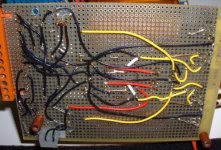
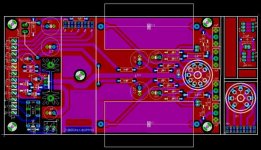
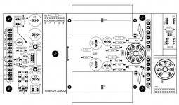
I did a design of a PCB for this tube section. Inspired from Guido Tent original HVSupply PCB it as these features:
-Support external supply transformers using an input terminal block.
-Support external CLC choke using insulated Molex connector
-Accept 6922 or 6N1P tube. You can install a bigger separate filament transformer for the higher 6N1P filament curren, select a different cathode resistor using jumper and the filament voltage regulator is mounted on a good heatsink.
-I added on the left over section of the PCB a small section to easily connect the DAC two leds and HV switch to the front panel.
Here the PCB schematic.
Attachments
- Status
- This old topic is closed. If you want to reopen this topic, contact a moderator using the "Report Post" button.
- Home
- Amplifiers
- Tubes / Valves
- My new tube DAC output