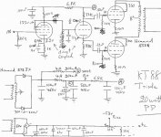
Oh Boy! A triode strapped KT88 amp. I have been enjoying mine for about 5 years now. Just retubed the KT88's with the same SED ones. The silver stuff was almost all gone inside the old ones. They were on about 10 hours a day on average for that long. I did a triode connected EF86 to a 12au7 split-load phase splitter => KT88's. I'll do up a crappy drawing (I can't draw!)and post it tonight. My B+ is about 420v and I get about 20w/ch out. I'm pushing a Hammond 272JX to supply both channels...we get a bit-o-sag on the B+ when both channels are pushed to 20w. I don't think that happens too often under regular listening..") MelB
MelB
MelBCheers!!
Yeh mine sags loads at the moment, the blue glow on the glass dissapears on peaks n the sound goes flat Ive noticed the getter disappearing fast on my valvearts. my amps on like your ten hours a dayish, but it's only been going a year. Already had one die too, jus stopped conducting. Anyways, lookin forward to your schematic!!
Steve
Yeh mine sags loads at the moment, the blue glow on the glass dissapears on peaks n the sound goes flat
Ive noticed the getter disappearing fast on my valvearts. my amps on like your ten hours a dayish, but it's only been going a year. Already had one die too, jus stopped conducting. Anyways, lookin forward to your schematic!! Steve
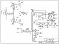
The new schematic seems just fine. But there are a few of those "i'd do it differently but it doesn't really matter" things. I would have bumped up the filter caps in the bias supply, and used a resistor since there is no need for a choke. I also typically put a small value capacitor from the wiper of the bias pot to ground, but it isn't needed. I also do not understand the filament winding fo the KT88's. I see a "virtual center tap" going to a capacitor, as if you were planning to put a DC bias on them to reduce hum, but I see no place where this voltage will come from. I'd just eliminate that capacitor and connect the "virtual center taps" to ground, output stages won't benefit from an elevated DC voltage on the heaters. Your driver tube has the center tap grounded, while filament induced hum will be essentially negligible here, you could put a DC bias on it from either one of the cathodes of that tube, or by added some extra rectification and stuff on the bias winding.
Looks like an awsome amplifier! be sure to take pictures
Looks like an awsome amplifier! be sure to take pictures
Hello,
Cheers Mel for going to all that trouble! very appreciated! Do you want to swap transformers? hehe, I want a center tap... Anyway, does it sound any better if you bias it a bit further towards class A? I've given my bias pots the ability to put voltage out from -30 to -45V in an effort to get more accuracy from the pots, maybe I should extend that to -55V for times when I'm not so worried about the quality....or my rooms getting too hot. Also do you know what primary impedance your outputs are?
Dr Photon cheers! Yes I'd like to have a bit more capacitance, I'll have to see how the funds go and if I've got anything left I can double up on the 75uF ones, space permitting as well. What does the small value cap on the bias pot wipers do? Just take noise to ground? Might be a good idea. For the heaters, I saw that 'virtual center tap' in a thread round here somewhere for getting rid of heater hum. Has to be done on the tube socket though I think or it doesn't work so well....I think, not sure of the reasons. I'll look into that a bit more I think as the simpler the better for me.
Cheers,
Steve
Cheers Mel for going to all that trouble! very appreciated! Do you want to swap transformers? hehe, I want a center tap...
Anyway, does it sound any better if you bias it a bit further towards class A? I've given my bias pots the ability to put voltage out from -30 to -45V in an effort to get more accuracy from the pots, maybe I should extend that to -55V for times when I'm not so worried about the quality....or my rooms getting too hot. Also do you know what primary impedance your outputs are?Dr Photon cheers! Yes I'd like to have a bit more capacitance, I'll have to see how the funds go and if I've got anything left I can double up on the 75uF ones, space permitting as well. What does the small value cap on the bias pot wipers do? Just take noise to ground? Might be a good idea. For the heaters, I saw that 'virtual center tap' in a thread round here somewhere for getting rid of heater hum. Has to be done on the tube socket though I think or it doesn't work so well....I think, not sure of the reasons. I'll look into that a bit more I think as the simpler the better for me.
Cheers,
Steve
Hi Steve:
I've never tried getting it up to class A. I'm limited by my power transformer here as it's rated 300-0-300 @250mA and it's driving both channels. I could try lowering the bias a tad I guess and run them at 50mA each. I never got around to that...I was just so happy with how it sounded at the time I left it. I do have an o-scope and can't "see" any cross-over distortion at 40mA. I don't think true class A is within my reach. If anyone could suggest an upgrade for a power transformer here. Something I've always wanted to do put never got around to. Looking for 320-300-0-300-320 maybe at >400mA that can also supply 6A @ 6.3v and will fit here: http://www.diyaudio.com/forums/attachment.php?s=&postid=570031&stamp=1107823338
The output trany's are 4.3K rated 60watts Hammonds. I must say they do a much better job on the finish of their output transformers than they do on their power transformers.
Missed a resistor on my drawing in the bias supply. Between the first cap and the 63v Zener is a 4.7K.
Hi,
Sowter maybe? Not sure about availability in Canada though, I'm sure they must have a distributer over there somewhere. For ultimate cheapness maybe a mains isolation transformer with a cover over it? 300v at 120mA maybe? We have 240v here, but I think most isolation transformers have dual windings so you could get round that. Would be less powerful though and you'd need seperate filament supplies, but they could sit inside if there's room. I like it as it is though, I think I recognise it from the photos thread? I think I saw a pic of the inside there too. Ill have a look round later. You could try EL34's as well, as as far as I know 40mA is a reasonable bias for them in p-p, looking at the curves they seem to work more linearly in triode at low current than the KT's do. Another option might be going SE with that transformer, and use the spare sockets for some valve rectifiers, but then less power, and a change of OP transformers and probably a totally different sound. Dunno... I like it as it is though! And I'm sure it must sound good, just a shame you haven't got much freedom on current.
Steve
I don't think that the virtual center tap resistors need to be located on the socket per se, just stick them wherever they fit. The socket is usually a conventient place since you can connect them from the heater pins to the cathode. In guitar amps, Fender typically mounted them on the pilot light. since you don't have any sensitive low level preamp-stages, the positive voltage on the grids shouldn't be necessary for hum reasons, I'd think. If you need more adjustment range and granularity, I'd recommend a multi turn pot. the little 10 or 15 turn PC board mounted trimmers have worked well for me (the kinds with the screw comming out one end). You can also get high quality 5 to 25 turn pots that mount like regular pots. These are typically high quality CTS or clarostat versions, usually blue plastic and sealed with very good "feel" to them. Just look around an electronics surplus store to find them.
Hi,
Cheers for the heater wiring suggestions,
Any thoughts on how to implement ac adjustment into this design, and wether it would be best to have the adjustment before or after the 6sn7's?
Also just thought I'd mention, I'm going to use S&B 896 line splitter transformers for phase splitting, hopefully these will do the job, would be nice to have some primary inductance figures though if anyone has these to hand?
Thanks,
Steve
oscillation
Hello there!
I've finally got round to building this now, Ill try and get some pictures done later.
For now though I have quite a large oscillation issue.
Each channels power supply is CLC filter for the output stage, with an additional LC for the driver.
They go:
rectifier, 20uF, 5H, 20uF, output tap, 5H, 5uF, driver tap.
Is this low capacitance in combination with the chokes likely to cause oscillation? It's running fine now with almost zero quiescent current, but as soon as I adjust the bias to raise the current it starts oscillating. If I short out the first 5H choke it's fine drawing current, but obviously i loose the choke then.
What should I do?
Thanks,
Steve
baggystevo82 said:FIIIIIXED!!!!!!!!!
Put an old 47uF lytic accross the middle cap in the power supplies. Sounding good now
happy happy happy happy happy happy!!!!
Steve
I notice some slight hints of happiness in your post...
Seriously, how does it sounds now? And how does it compares to a SE of KT88?
Yes a little bit!!!
Well putting that extra cap in the power supply has allowed me to get up to 60mA before it starts oscillating, so I'm just running it at 55mA where it seems completely stable. I guess following that trend I can add more capacitance and I will be able to run more current. Is this what motorboating is?
Anyway as for the sound....
I haven't built it a preamp yet, so at the moment I'm either running it from my computer, direct from the cd player (which sounds awesome, just a little loud for everyday listening...) or using my headphone amp (mini zen) as a preamp, which is what I'm mostly listening to at the moment.
It sounds much cleaner than the old amp, even on only 55mA. I had intended running between 80 and 100mA @ around 370V which I hope will sound even better. Bass is rediculous compared to the original circuit, maybe it's because of the 1uF coupling caps or something. The input transformer (now a pair of Neutrik NTL-1) has 150H primary inductance, which has a very good low frequency response with the impedences I'm driving it with. I fancy trying a bit of NFB to see the effect on bass at higher volumes, I think I might need an extra gain stage then though.
The most interesting thing so far I think is I put a pair of switches on to change from UL to triode mode, and the amp/speakers don't seem to mind this being changed on the fly, it rarely even makes a click. Difference in sound is quite large though on immediate A/B comparison. Triode has much thinner bass, but after a few minutes of acclimatization sounds more neutral. Still no substitute for UL at high SPL's though. Maybe switchable NFB would be a nice thing to add too, though I need help on how to apply NFB with this topology...
Thanks,
Steve
It sounds indeed like motorboating. If increasing current to 60mA starts it up, you're running on the edge of instability and ought to take appropriate measures- decoupling between stages is generally the first step. And added NFB will only make the problem worse until it's fixed.
Hi SY,
Yes it definitely needs addressing. There's a 5H choke between output and driver stage supplies if that's what you meant, but only a little 5uF cap which I think needs increasing. Shouldn't be too much trouble to sort out. Did you end up trying LED's for biasing much in the end? I'll have to try putting a flourescent lamp next to them sometime and see if there's much noise... The amps silent as silent gets at the moment though.
Cheers,
Steve
I've been using LEDs for cathode biasing EL84s in a little prototype amp. It seems to work very, very well. With KT88s, that's unfortunatley impractical.
In any case, one decoupling trick (besides brute force) is to take your chokes separately from the raw B+ point instead of putting them in series. The real answer is separate input stage regulation...
In any case, one decoupling trick (besides brute force) is to take your chokes separately from the raw B+ point instead of putting them in series. The real answer is separate input stage regulation...
- Status
- This old topic is closed. If you want to reopen this topic, contact a moderator using the "Report Post" button.
- Home
- Amplifiers
- Tubes / Valves
- My new pp KT88 design