Hi All,
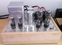
Here is a picture of my Darius Loftin-White prototype with the original "test" OPT's. The top plate is a standard 35cm x 25cm - I usually employ two of these chassis for push-pull amplifiers, so was surprised that the Loftin-White could fit in a single one! or so I thought.....
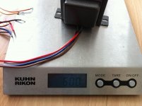
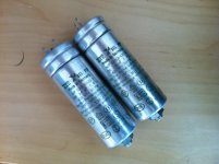
The "test" OPT's are little 6 Watt japanese things. I painted them a while back so they don't look quite so ugly... They weigh in at a lowly 600g apiece. Since getting back into building single-ended I forgot that the iron can get BIG very fast....
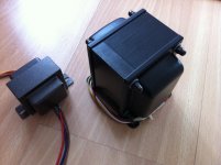
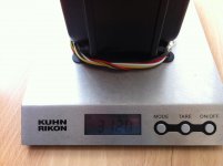
Look at what will probably be the new finals. They are over 3Kg apiece! I have to re-do my whole layout now... 35cm x 25cm will be a tough fit! I'm kinda looking forward to a re-work.
Anyway the mains transformer cover and top plate are not pretty either so will get swapped out for something much nicer too.
I thought you might enjoy the contrasting size of the OPT's
Here is a picture of my Darius Loftin-White prototype with the original "test" OPT's. The top plate is a standard 35cm x 25cm - I usually employ two of these chassis for push-pull amplifiers, so was surprised that the Loftin-White could fit in a single one! or so I thought.....
The "test" OPT's are little 6 Watt japanese things. I painted them a while back so they don't look quite so ugly... They weigh in at a lowly 600g apiece. Since getting back into building single-ended I forgot that the iron can get BIG very fast....
Look at what will probably be the new finals. They are over 3Kg apiece! I have to re-do my whole layout now... 35cm x 25cm will be a tough fit! I'm kinda looking forward to a re-work.
Anyway the mains transformer cover and top plate are not pretty either so will get swapped out for something much nicer too.
I thought you might enjoy the contrasting size of the OPT's
Attachments
Last edited:

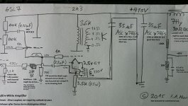
The schematic was surprisingly easy to create. No need for any simulation software - I basically did it on the back of an envelope... The anode resistors on the input 6SL7 were chosen to achieve the bias point needed for the 2a3. To make the math simple, I chose to bias the input 6SL7 triode at 1mA. I actually calculated the "triode characteristic factor" after designing the initial circuit - just to make sure it really would not need cathode bypass. The "triode characteristic factor" is somewhere around 40 with this design, so there is absolutely no need for any cathode bypass.
My prototype sounded ROUGH at first. Then I adjusted the noise cancellation network accordingly. That took a little bit of time since the multi-turn 20k potentiometer on my prototype has a tiny little screw. I haven't needed to adjust it since then though. No input/driver tube swapping with this schematic - unless I feel the urge to fiddle with the 20k pot again. No reasonable way to make it 2a3/45 switchable either.
The noise cancellation caps are fairly cheap ERO MKT 1813 film caps. The New transformers pictured above are from J&K http://jandkaudiodesign.blogspot.com who I can recommend for thorough explanations of their transformer design and winding techniques.
look at how fine the laminations are on the new OPT's..... I am certain they will sound amazing!
I also have some nice Hirata Tango XE-20s here that I will be testing out. To be honest though, the sound is already pretty impressive with these little 6 Watt OPT's...
The wonderful thing about this amp is this: Instead of spending money on expensive hand-made beeswax filled coupling capacitors and exotic cathode bypass solutions, you can stick simply stick your money in highest quality transformers. You might even notice that the tubes in my protoype are not expensive variants.
The power transformer and choke are from Thomas Mayer http://vinylsavor.blogspot.com who I can also highly recommend for sound advise. I doubt he will build an amp like this but you never know!
Last edited:
For reference: This adaptation of Loftin-White comes from Darius Loftin White: ECC83 300B Darius Loftin White
Last edited:
Great presentation of your latest stuff here. Thanks for the link to the J&K guys, I will take a deep look at their site to see what they have to offer.
What are those rectifiers you are using in the pictures of your build (post #1)?
Looking forward to your listening experience with the new iron.
Cheers, GB
What are those rectifiers you are using in the pictures of your build (post #1)?
Looking forward to your listening experience with the new iron.
Cheers, GB
The rectifiers are 6DA4 tv damper diodes in a graetz bridge (with two 1N4007 since the transformer has no center tap). There are others you can use of course... Thomas Mayer often uses 6AX4. 6AU4 are also very nice so long as you can handle the extra heater current.
I was cleaning office a couple of months ago and came across whole box of 6DA4's that I had completely forgotten about... all in sleeves of 5 - never used.
I was cleaning office a couple of months ago and came across whole box of 6DA4's that I had completely forgotten about... all in sleeves of 5 - never used.
The power transformer and choke are from Thomas Mayer VinylSavor who I can also highly recommend for sound advise.
I got one of his power transformers for a project I recently started. It's very nice! I think I'll get a few more for future projects.
I'm also looking forward to reading your comparison between the old and new output transformers.
These JK transformers look tidy wound. That is how a winding should look. Multislot winding or single slot?The New transformers pictured above are from J&K J&K Audio Design[/B] who I can recommend for thorough explanations of their transformer design and winding techniques.
look at how fine the laminations are on the new OPT's..... I am certain they will sound amazing!
I also have some nice Hirata Tango XE-20s here that I will be testing out. To be honest though, the sound is already pretty impressive with these little 6 Watt OPT's...
I am not a big fan of teflon but this can be a solution when one is not willing to impregnate the windings. Teflon has good mechanical damping.
I am also very curious to know how these will compare to Tango XE20
Looks better than an anonymous computer drawn schematicHere is the schematic I currently using. Sorry that it is drawn in chicken scratch.
A part of PS is not visible, do you use inductive input filter or is there an input capacitor?
2A3 cathode resistor 3,5K is bypassed with 17,5uF to ground (two 35uF in series). About "ultrapath" capacitors nothing here.
BTW, old and long story is: is Ultrapath capacitor in the signal path. Consensus is: YES, Ultrapath cap is in the signal path. Who is interested, a search on this or any other audio forum.
BTW, old and long story is: is Ultrapath capacitor in the signal path. Consensus is: YES, Ultrapath cap is in the signal path. Who is interested, a search on this or any other audio forum.
Attachments
...no comment ??
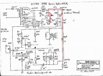
Now let's look at Darius 300B L-W scheme.
There is also no Ultrapath capacitor. 300B cathode resistor R7 (3K3) is baypassed with 2-3 uF!!! to ground {60uF + 8uF (+ 4,5uF)} all in series.
But of course, if someone enjoys in sound of this amplifier, it is quite OK.
Now let's look at Darius 300B L-W scheme.
There is also no Ultrapath capacitor. 300B cathode resistor R7 (3K3) is baypassed with 2-3 uF!!! to ground {60uF + 8uF (+ 4,5uF)} all in series.
But of course, if someone enjoys in sound of this amplifier, it is quite OK.
Attachments
Last edited:
Looks better than an anonymous computer drawn schematic
A part of PS is not visible, do you use inductive input filter or is there an input capacitor?
LC
2A3 cathode resistor 3,5K is bypassed with 17,5uF to ground (two 35uF in series). About "ultrapath" capacitors nothing here.
BTW, old and long story is: is Ultrapath capacitor in the signal path. Consensus is: YES, Ultrapath cap is in the signal path. Who is interested, a search on this or any other audio forum.
RajkoM, yes the PSU is always in the signal path - this is not new at all... It is also there in the original 1929 Loftin-White schematic.
I could make C2 smaller if that is what you are suggesting? I think Sheldon only used 8uF in his version. I just don't have a smaller value at the moment...
Last edited:
...no comment ??
Now let's look at Darius 300B L-W scheme.
There is also no Ultrapath capacitor. 300B cathode resistor R7 (3K3) is baypassed with 2-3 uF!!! to ground {60uF + 8uF (+ 4,5uF)} all in series.
But of course, if someone enjoys in sound of this amplifier, it is quite OK.
Darius also used CLC network which is not my cup of tea. But that is what diyaudio is all about!
Which 20K pot do you use? I am uncertain about wattage requirement.
I used a cermet multi-turn pot. Multi.turn is a good idea to dial in the right level of noise cancellation. mine is quarter watt.
...no comment ??
I am not sure what your point is, but hope it is constructive and in the spirit of diyaudio... I could easily make C2 and C3 smaller if that is what you are suggesting.
Ok I just tried out this change now You can easily make C2 much smaller as I believe RajkoM suggests. If you do this, you will likely need to adjust the 20k pot a little bit. B+ will go down to maybe 390V, but that is still good.
I am doing some listening and the first impression is that it makes little sonic difference.... Bass response, transients, imaging is still wonderful as before. Should it maybe be better? Hard to tell...
Thre is an added benefit is that I now have more room in the chassis.
You can easily make C2 much smaller as I believe RajkoM suggests. If you do this, you will likely need to adjust the 20k pot a little bit. B+ will go down to maybe 390V, but that is still good.I am doing some listening and the first impression is that it makes little sonic difference.... Bass response, transients, imaging is still wonderful as before. Should it maybe be better? Hard to tell...
Thre is an added benefit is that I now have more room in the chassis.
Last edited:
...no comment ??
Your thinking appears to be wrong. The ultrapath cap shorts the output stage AC current path directly to B+, and that's it. Of course, it's in the audio path. But it takes the PSU out of the audio path. It's also not in series with any other cap.
- Status
- This old topic is closed. If you want to reopen this topic, contact a moderator using the "Report Post" button.
- Home
- Amplifiers
- Tubes / Valves
- My New Iron for Single Ended 2a3