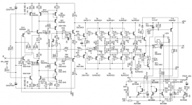
I'm workign to build a new hybrid amplifier with tube input stage, and ss buffer. The estimated output power is 300W/4ohms, and the output buffer design based on Marantz PM11S1 output stage. But my version use more and different output devices.
The voltage gain of the buffer is 3. Simulated distortion is 0.003% at 300W output power.
The input stage based on single 6H30P for both channels. Voltage gain is approx. 6.
Sajti
The voltage gain of the buffer is 3. Simulated distortion is 0.003% at 300W output power.
The input stage based on single 6H30P for both channels. Voltage gain is approx. 6.
Sajti
I'm workign to build a new hybrid amplifier with tube input stage...
wow!
please show!
I'm workign to build a new hybrid amplifier with tube input stage, and ss buffer. The estimated output power is 300W/4ohms, and the output buffer design based on Marantz PM11S1 output stage. But my version use more and different output devices.
The voltage gain of the buffer is 3. Simulated distortion is 0.003% at 300W output power.
The input stage based on single 6H30P for both channels. Voltage gain is approx. 6.
Sajti
If that buffer is push-pull and includes several stages, emloying tube input stage will insignificantly improve the final sound, it is already determined by the buffer, IMHO.

If that buffer is push-pull and includes several stages, emloying tube input stage will insignificantly improve the final sound, it is already determined by the buffer, IMHO.
Hi,
yes it can be. I want to try.
The THD of the output stage is 100 times lower than the THD of the tube driver stage. And the distortion mainly 2nd harmonic.
Sajti
Aikido or White follower at the input?
You can use any of them, but not necessary. The input impedance of the buffer is 100kohms, with only few pF input capacitance. I plan to use simple common cathode stage.
Sajti
Beautiful design, Sajti. I see the output buffer is error corrected, wow!
Hugh
Hi Hugh
thanks! Unfortunately the quality of the schematic is not quite good, because I have to reduce the size, for another forum. So there is no error correction at the output. The small transistors are working as overcurrent protection.
Sajti
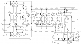
I see now, it's a conventional EF3 output stage, with EF input stage to a complex complementary singleton drive via a current mirror and a cascode to the pre-driver. Fascinating protection system! Not simple at all, I assume very high OLG and very low THD? How does it sound, does it make you tap your feet and bring out a smile?
Hugh
Hugh
I see now, it's a conventional EF3 output stage, with EF input stage to a complex complementary singleton drive via a current mirror and a cascode to the pre-driver. Fascinating protection system! Not simple at all, I assume very high OLG and very low THD? How does it sound, does it make you tap your feet and bring out a smile?
Hugh
So, the OLG is about 500. It can be higher, but I don't think that it's necessary. The OLG distortion is 0.22%, with 4ohm load, and 300W output. Mainly 3rd harmonic. Interesting that the closed loop distortion contains mainly 2nd harmonic.
The protectione system is my own development, and contains delayed switch ON, overcurrent, overtemperature, low voltage protection. Self reseting, and the amplifier can handle the short circuit for long time.
The circuit based on Marantz PM11, or MA9, but I try to use better passive components.
Not yet listened, I need some more time to build the PSU, and the tube input stage.
Sajti
- Status
- This old topic is closed. If you want to reopen this topic, contact a moderator using the "Report Post" button.
- Home
- Amplifiers
- Solid State
- My new hybrid amplifier