Here ya go:
http://dl.dropbox.com/u/5430178/circlophone/circlophone_fix_3 - Bottom Black_With Drill.pdf
http://dl.dropbox.com/u/5430178/cir...ix_3 - Bottom Copper_Drill_Top Silkscreen.pdf
Keep in mind I forgot the layer with the jumper wires. But you can look at wakabaki's posted thumbnail for those.
EDIT: Temporarily ignore those. I just noticed what I think is a big error.
Wakabaki, your thumbnail shows several traces that are not seperated at all from the groundplane that surrous them. In the gerber files, they do not show up at all. Am I missing something?
Nevermind, all is good.
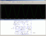
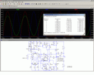
Here is the confirmation of what I said earlier, and also of the versatility of the Circlophone's topology:
I simply dropped two NMOS in place of the darlingtons, in the Ndarlington version, and it worked exactly as expected.
The only things that required adaptation are the G-S resistors that have been increased to 390ohm.
Also, the lower clipping value predicted on the positive side is observed: the clipping occurs ~5V below the positive rail.
If the input voltage is reduced to just under the clipping, the behavior becomes almost identical to that of the BJT version: the THD is a bit higher, probably because of the lower transconductance of the MOS compared to the bipolars.
The bias servo too works in an identical manner.
A reminder:
all this is simulation, and nothing has been built yet.
But I will come up with a version using the same trick as the CircloMOS, build it, and launch a dedicated thread when it's mature and working well enough.
Attachments
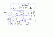
Because that's the view of the topology I am more familiar with.Why are the later circuits, particulary the last one upside down ? A bit confusing.
But I understand it can be confusing to others.
Here is a more habitual presentation:
Attachments
No, it mainly has to do with the power supply: without D3 and D4, Q5 would see an almost constant voltage equal to 2*Vsupply.Hi elvee,
What is the main purpose of the 2 zeners in series (D3+D4 in last schema), in first schema value was 24v (12v+12v) but in darlington and MOS version it was reduced to 18.2 v (10v+8.2V)? Does the Threshold voltages differences comes to play here?
On the other hand, Q6 sees the full output swing, with an average equal to Vsupply.
This means that Q5 would dissipate on average twice as much power as Q6.
Adding ~Vsupply worth of zener decreases the dissipation of Q5 to the level of Q6.
This improves the static balance of the phase-splitter, and avoids the need of a heatsink for Q5.
The first schematic is shown with 25V supplies, whilst the other one uses 20V rails.
This balancing is purely static, and does nothing for the dynamic asymmetries caused by the Early effect.
It might be advantageous to replace the zeners by a resistor, but I haven't (yet) explored that option.
Many other TO5/TO39 and VAS-type transistors are also suitable, the 2N3019 is not at all criticalToday I will etch a board, and populate most of it. I will just have to get some 2N3019s and the schottky diodes.
Last edited:
No, it mainly has to do with the power supply: without D3 and D4, Q5 would see an almost constant voltage equal to 2*Vsupply.
On the other hand, Q6 sees the full output swing, with an average equal to Vsupply.
This means that Q5 would dissipate on average twice as much power as Q6.
Adding ~Vsupply worth of zener decreases the dissipation of Q5 to the level of Q6.
This improves the static balance of the phase-splitter, and avoids the need of a heatsink for Q5.
The first schematic is shown with 25V supplies, whilst the other one uses 20V rails.
This balancing is purely static, and does nothing for the dynamic asymmetries caused by the Early effect.
It might be advantageous to replace the zeners by a resistor, but I haven't (yet) explored that option.
Many TO5/TO39 and VAS-type transistors are also suitable, the 2N3019 is not at all critical
Already ordered from Mouser. I needed other things as well, and decided I might as well use those.
No, it mainly has to do with the power supply: without D3 and D4, Q5 would see an almost constant voltage equal to 2*Vsupply.
On the other hand, Q6 sees the full output swing, with an average equal to Vsupply.
This means that Q5 would dissipate on average twice as much power as Q6.
Adding ~Vsupply worth of zener decreases the dissipation of Q5 to the level of Q6.
This improves the static balance of the phase-splitter, and avoids the need of a heatsink for Q5.
The first schematic is shown with 25V supplies, whilst the other one uses 20V rails.
This balancing is purely static, and does nothing for the dynamic asymmetries caused by the Early effect.
It might be advantageous to replace the zeners by a resistor, but I haven't (yet) explored that option.
Thanks for the explanation now i got it, so the values are dependent on the desired rail voltages and balance of the 2n3019's.
BTW, what is the maximum rail voltage allowed assuming output transistors are changed to higher Vce/Vds types. Let's say at +/- 50volts what components needs upgrading?
You should find information about the components dimensioning in this post:Thanks for the explanation now i got it, so the values are dependent on the desired rail voltages and balance of the 2n3019's.
BTW, what is the maximum rail voltage allowed assuming output transistors are changed to higher Vce/Vds types. Let's say at +/- 50volts what components needs upgrading?
http://www.diyaudio.com/forums/solid-state/189599-my-little-cheap-circlophone-6.html#post2591420
Going much higher than +/-50V would make little sense: even on 8 ohm, this would mean an output power in the region of ~150W, which is clearly unreasonable for a single pair of output transistors.
Even the most rugged types, like the 2N6259 would be pushed to their limits.
I don't recommend paralleling transistors on this design: emitter degeneration resistors would be needed, and they would interfere with the constant transconductance action provided by the bias servo.
This would create crossover artifacts similar to those of a standard class AB output stage.
The optimum range of power for this design is between ~10 to 100W.
View attachment 225174
View attachment 225180
View attachment 225181
w
If you see anything else don't hesitate to point it out.
Wakibaki,
May I have your permission to post your PCB files on another forum?
I would acknowledge your authorship, of course.
Getting populated:
http://dl.dropbox.com/u/5430178/project pics/Circlophone/populating PCB.jpg
I am using the 2N3019, and BC546/556 (C). I used 1N5822 and BAT85 for the schottky's. The outputs will be MJ802. The drivers 2SB649.
Just have to find some of these capacitors.
http://dl.dropbox.com/u/5430178/project pics/Circlophone/populating PCB.jpg
I am using the 2N3019, and BC546/556 (C). I used 1N5822 and BAT85 for the schottky's. The outputs will be MJ802. The drivers 2SB649.
Just have to find some of these capacitors.
Some news:
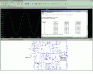
I have tested (in sim) the idea of replacing the zeners with a resistor.
The result is disappointing: the change in linearity is insignificant, and for the worst.
It looked like a good idea in theory, but it doesn't deliver, and if there is no improvement in sim it's probably not worth testing in reality.
In addition, it would probably upset the compensation and degrade the dynamic performances.
Attachments
Elvee, what about these transistors? I have no TO-3 heatsinks, and I feel that I probably couldn't make the best mounting for TO-3 on a regular heatsink. These transistors would make it that much easier: MJW21196
https://www.onsemi.com/pub/Collateral/MJW21195-D.PDF
fT=4MHz. Right on the line according to your guide. Would it work with C12=180+pF and C11 not installed? I will probably just have to try it...
https://www.onsemi.com/pub/Collateral/MJW21195-D.PDF
fT=4MHz. Right on the line according to your guide. Would it work with C12=180+pF and C11 not installed? I will probably just have to try it...
It should be OK.Elvee, what about these transistors? I have no TO-3 heatsinks, and I feel that I probably couldn't make the best mounting for TO-3 on a regular heatsink. These transistors would make it that much easier: MJW21196
https://www.onsemi.com/pub/Collateral/MJW21195-D.PDF
fT=4MHz. Right on the line according to your guide. Would it work with C12=180+pF and C11 not installed? I will probably just have to try it...
Of course, since this exact type of transistor has never been tested in any of the prototypes, and the layout is different, I cannot give a 100% guarantee.
Never take anything for granted.
To be on the safe side, I would recommend you first try with C11 installed, and when you're satisfied everything works as expected (which it should), you can begin to tweak, make comparisons with/without the cap, and decide for yourself what's the best option.
When you install C11 and it's not needed, there is an infinitesimal degradation of the transient performances, but it is really very very small: the oscilloscope screenshots and the measurement have been made with C11 in place, and it was not really needed, since 2N3055's were used.
You can see for yourself that it still very good, and implementing the capacitor buys you peace of mind.
Anyway, even if oscillations do break out, they should be of a small amplitude and very high frequency, and pose no threat to tweeters or the amplifier itself.
With the MJW21196's, you will have an incredibly robust amplifier, even without protection: their SOAR is quite impressive
During the tests, I had some "accidents", but never succeeded in blowing the OP transistors.
With the MJW's, it will be positively bullet-proof.
It should be OK.
Of course, since this exact type of transistor has never been tested in any of the prototypes, and the layout is different, I cannot give a 100% guarantee.
Never take anything for granted.
To be on the safe side, I would recommend you first try with C11 installed, and when you're satisfied everything works as expected (which it should), you can begin to tweak, make comparisons with/without the cap, and decide for yourself what's the best option.
When you install C11 and it's not needed, there is an infinitesimal degradation of the transient performances, but it is really very very small: the oscilloscope screenshots and the measurement have been made with C11 in place, and it was not really needed, since 2N3055's were used.
You can see for yourself that it still very good, and implementing the capacitor buys you peace of mind.
Anyway, even if oscillations do break out, they should be of a small amplitude and very high frequency, and pose no threat to tweeters or the amplifier itself.
With the MJW21196's, you will have an incredibly robust amplifier, even without protection: their SOAR is quite impressive
During the tests, I had some "accidents", but never succeeded in blowing the OP transistors.
With the MJW's, it will be positively bullet-proof.
Good to hear! Should have them soon then (hopefully).
What's the minimum input power?
I want to run two channels on a 160VA traffo, don't need lots of power.
I also play to use a 160va trafo. I feel it will be sufficient.
I also play to use a 160va trafo. I feel it will be sufficient.
Are you going to regulate it down at all?
Are you going to regulate it down at all?
I have some high current regulator pcbs I made a while ago. Just simple 317/337 + pass transistors. The trafo will put out about 36VDC before regulation to 25(+-). Speakers will be 8 ohms only as well. Amp will only see light/medium duty for mostly movies in the bedroom. They were used on LM3886 for over a year now. They are adjustable also. Now that I think about it the trafo may be 200VA. I know the 11 volt reg drop isn't optimal, but the pass transistors work out. I could always run a bit higher than the 25 I think.
- Home
- Amplifiers
- Solid State
- ♫♪ My little cheap Circlophone© ♫♪


