I would really like to discuss regulated power supply for Circlophone, especially since the Philips BD140 gets sketchy at higher voltage and is vulnerable to power surges if run unregulated. But that's just an excuse. Regulated power has a different sound, usually a great quality baritone region, and I'd like to try that. Capmulti can do the same, but I don't have an excuse to ask for that. ")
I didn't care to make the rest of the modifications, and connected it to a source and speaker: as I write, I am listening to it and everything seems OK
CFP version hasn't zeners in scheme (I don't know why). Were they in place when you testing?
The zeners can range from total voltage span (no zeners present) to half of total voltage span (as shown in post 1 and post 658). The difference is apparently heat in one of the drivers. And you want to use the zeners. I guess and predict that he will answer yes, he was using the zeners, as shown in post 1.
What I'm unsure of is the connection of the R18+C12 RC when the zeners are installed (and they should be). It appears that the RC is for assisting the drivers, which is not exactly what the schematic (post 1 and post 658) shows since the RC may be less effective when isolated by those diodes. So, I'd like to add that question. Should the RC go directly between the divers instead, for post 1 and likewise post 658?
What I'm unsure of is the connection of the R18+C12 RC when the zeners are installed (and they should be). It appears that the RC is for assisting the drivers, which is not exactly what the schematic (post 1 and post 658) shows since the RC may be less effective when isolated by those diodes. So, I'd like to add that question. Should the RC go directly between the divers instead, for post 1 and likewise post 658?
Last edited:
I would really like to discuss regulated power supply for Circlophone, especially since the Philips BD140 gets sketchy at higher voltage and is vulnerable to power surges if run unregulated. But that's just an excuse. Regulated power has a different sound, usually a great quality baritone region, and I'd like to try that. Capmulti can do the same, but I don't have an excuse to ask for that.
I was investigating how easily one could fudge an undervoltage lockout.
In case one power supply is up, the other not (fuse blown or whatever).
Amazingly, I find circlophone needs none! You can disconnect either
supply from it's rail, and nothing bad happens. Accident of genius?
It also tolerates the case of positive supply shorted to GND.
Does not, however tolerate the negative supply shorted to GND.
What would it take to make that condition safe too, just a diode?
No, that shouldn't cause any problem. It will make the input resistance even higher.Has anyone any idea of possibility of degrade something if using relatively high gain transistors as input pairs in CFP version?
Nice power supplies?
I'd like to hear about some deluxe power supply options for both regulated and unregulated power that are really good with Circlophone.
Of course Circlophone does perform well with a really basic power circuit, and although that is true, I am curious about clean power, and I am especially curious about decreasing the harmonic influence of the power supply, by using a clean / higher quality power supply.
Last edited:
I'd like to hear about some deluxe power supply options for both regulated and unregulated power that are really good with Circlophone.
Of course Circlophone does perform well with a really basic power circuit, and although that is true, I am curious about clean power, and I am especially curious about decreasing the harmonic influence of the power supply, by using a clean / higher quality power supply.
Like most decent amplifiers, the Circlophone needs no regulated power.
At best, a regulated power supply will not change anything, but in most cases (that is particularly applicable to "audiophiliacs" supplies), it will do some harm, because of an uncontrolled output impedance or downright instabilities, like in this example.
I guess this one must seriously "enrich" the harmonic balance of whatever it supplies:
Attachments
If the amplifier is dead quiet at idle, prevented from clipping,
drives all stages entirely by high impedance currents rather
than low impedance voltages: When would it be interacting
with reasonable amounts of low frequency power supply ripple?
This is painting "enable" dots on the edge of a CD. The last
resort of someone with far too much time on their hands.
I see a lot of "simple" amplifiers that want 4 or more complex
supplies of absurd cleanliness. I don't perceive any advantage
designing amplifiers to lean upon a crutch of such requirement.
Last edited:
I'd like to hear about some deluxe power supply options for both regulated and unregulated power that are really good with Circlophone.
Of course Circlophone does perform well with a really basic power circuit, and although that is true, I am curious about clean power, and I am especially curious about decreasing the harmonic influence of the power supply, by using a clean / higher quality power supply.
Attachments

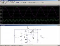
If one needs to limit the voltage to a level safe enough for the transistors, here is an option (but, of course, it shifts the Vceo requirement to the supply transistors).
It is crude, minimal, but will not play silly tricks unlike the previous example.
It also includes a foldback limiting.
Hope this settles the matter once and for all.
It is crude, minimal, but will not play silly tricks unlike the previous example.
It also includes a foldback limiting.
Hope this settles the matter once and for all.
Attachments
Other option, why not opt for an (almost) existing, nice, sophisticated design like this one:
http://www.diyaudio.com/forums/powe...ply-cap-multiplier-electronic-protection.html
A bit complicated, but that's also part of the charm.
I personally prefer to concentrate my efforts on the amplifier, making that kind of accessory redundant, but that's a matter of taste.
http://www.diyaudio.com/forums/powe...ply-cap-multiplier-electronic-protection.html
A bit complicated, but that's also part of the charm.
I personally prefer to concentrate my efforts on the amplifier, making that kind of accessory redundant, but that's a matter of taste.
If you build the CFP version, you should use the specific CFP compensation components.
Doing otherwise would compromise stability.
Be careful anyway, contrary to the original Circlophone, that variation has undergone only minimal tests, and there could be unpleasant surprises.
Make the first tests on a dummy load to be sure not to toast your tweeters
Doing otherwise would compromise stability.
Be careful anyway, contrary to the original Circlophone, that variation has undergone only minimal tests, and there could be unpleasant surprises.
Make the first tests on a dummy load to be sure not to toast your tweeters
I have applied CFP version to powerflux pcb. It works fine with specific compensation values. But I haven't applied the network at feedback resistor, so could you confirm that it should be ok or less critical than other alterations? I know that I have to respect the scheme as what it is but I would ask this one due to space requirements on pcb.
It is stable in that configuration, that's how I physically tested it, but simulation shows a very narrow stability margin.I have applied CFP version to powerflux pcb. It works fine with specific compensation values. But I haven't applied the network at feedback resistor, so could you confirm that it should be ok or less critical than other alterations? I know that I have to respect the scheme as what it is but I would ask this one due to space requirements on pcb.
For stable and safe operation, the new values should be applied (with caution, as this has only been tested in sim).
That is looking really elegant.A slightly improved version of the supply:
I've got a few questions:
Does it reduce ripple?
Can it be set to 40v?
What happens if input voltage is lower than the zener?
Thanks!
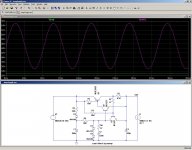
Yes, the sim shows the circuit in full action: the magenta trace is the input voltage having a 20V/120Hz ripple level, and the output is simultaneously loaded by a current varying from 0.5 to 2.5A at 1KHz.That is looking really elegant.
I've got a few questions:
Does it reduce ripple?
Even under those conditions and a 2V operating margin, the rejection remains good.
Yes, any zener or combination of zeners giving that voltage is suitable: 39V if 1V is not a problem, or two 20V, or 18V+22V, etc.Can it be set to 40v?
It degenerates into an electronic filter (not with the insane level of ripple shown there: with a more normal level of several volts):What happens if input voltage is lower than the zener?
Attachments
- Home
- Amplifiers
- Solid State
- ♫♪ My little cheap Circlophone© ♫♪