unbeliavle how important are inductors and 1.5 ohm resistors
I still can't get that trick to work... Would base resistors help?
as above,
cannot make this...
there is no txt extension in the name, but the file has txt in the properties...
in XP I was able to make it, but under Vista or W7 impossible... or I do not know how...
I will try to make this in win commander or similar,
thanks
PS Total commander has option to change the extension, I solved the problem, sorry for offtopic
You can edit you're folder properties to view the extensions of files (.txt;.avi;.asc;etc.)
Here (first google result): How do I show file extensions in Windows XP?
Similar method to do this in other windows versions. Now you can change extensions in windows explorer very easily.
Unrelated to above:
This thread may be slightly confusing to people who are new to it. They may think that the circlophone is one of the other couple schematics posted here, or may think it is unfinished or other. Or maybe I am wrong.
Last edited:
You can edit you're folder properties to view the extensions of files (.txt;.avi;.asc;etc.)
Here: How do I show file extensions in Windows XP?
Similar method to do this in other windows versions. Now you can change extensions in windows explorer very easily.
Thanks
as I wrote before I know how to do this in XP
but Vista or W7 are different.
anyway I did it in total commander and the problem is solved.
Thanks
as I wrote before I know how to do this in XP
but Vista or W7 are different.
anyway I did it in total commander and the problem is solved.
Sorry, read to quickly I guess.
You are probably right: to a newcomer, it must look like a ragbag of unrelated things and subjects.Unrelated to above:
This thread may be slightly confusing to people who are new to it. They may think that the circlophone is one of the other couple schematics posted here, or may think it is unfinished or other. Or maybe I am wrong.
It would probably be a good idea to put some order into that, perhaps by creating an index or something of the sort, I'll try to think about it.
_________________________________________________
Anyway in the mean time, here is the message to the newbies:
The schematic in #1 is still current and up to date, PCB files can be found in #53, useful construction info in #56, pdf's of the pcb are in #59, a short explanation on how the servo works is here #106, #182 is a selection guide for different power versions.
Another PCB version is currently under development and should be released soon.
________________________________________________
You mean you loaded my asc file and it doesn't work?I still can't get that trick to work... Would base resistors help?
If that's the case, it can only be your LTspice settings are different than mine.
Mine are all defaults: normal solver, modified trap, etc.
Note that base resistors will make things worse for stability: the circuit will reverse them, making them negative.
You bet they're important: without them, the Xquad has an infinite gain at all frequencies, including infinity.unbeliavle how important are inductors and 1.5 ohm resistors
Not the straightest path to unconditional stability.
As you rely only on the bead's losses for damping, that's understandable.This thing is on the hairy edge of unstable.
And the beads do nothing to combat the negative resistance inherent to the circuit.
For stability, a degeneration resistor of minimum Rin/β is required. With ~470Ω, that's ~1Ω.
If you want to go even further in that direction (linearizing the LTP), another method is to use a crossquad.
The beast is difficult to tame, but it's worth the trouble:
THD @1W 1KHz can easily be pushed deep below the ppm threshold...
Hi Elvee
was it a trick to fool the simulator
or will work in practice?
Substitute a slightly mismatched transistor across the quad,
and watch voltage offset at the output change many volts!
Granted, offset is multipled by 20, cause I neglected to add
DC blocking in the feedback loop. Probably not unmanagable.
On second though, that was idiotic of me. Any mismnatched
LTP will offset about the same, what was I thinking???
I was expecting offset to latch first one way, then the other.
But I could not get it to flip after it had taken a preference.
And the simulated distortion remained extremely low. I now
think this problem exists only in my imagination.
Last edited:
It is definitely not a trick played with the simulator.Hi Elvee
was it a trick to fool the simulator
or will work in practice?
Now, will it work in practice?
Yes, but your mileage may vary.
The crossquad is a pretty temperamental circuit, relying on a precisely controlled amount of positive feedback to function, and that feature plus the parasitics of real world circuits make an interesting mix...
If you build the circuit exactly as on the schematic, it will probably oscillate like mad.
If you try the usual recipes to tame the oscillations, like base stoppers and similar, not only will they not cure the problems, they will make them much worse: at the bases of the input transistors, a negative resistance of Re-e/Hfe is created.
If that negative resistance is parallelled with a positive one (the source impedance) larger than itself, the resulting equivalent resistance is negative too, with results you can imagine.
By adding base stoppers, you increase the source resistance, making the problem worse.
And because the Hfe drops at high frequencies, input resistances much smaller than expected can cause problems.
One solution is to bypass the base with a small value cap, to reduce the apparent impedance at high frequencies.
That's just an example. There are a number of other mechanisms leading to oscillations.
The compensations of the amplifier itself need to be adjusted, to take into account the effects of the Xquad in the overall loop.
It is not a simple task, but it is doable. I have made functionning designs based on a crossquad (not in the Circlophone though).
Some other pecularities have to be remembered: the phase is reversed compared to a standard LTP, but when it saturates, it degenerates and reverts to the normal phase.
And it only takes several hundreds mV to saturate, however large is the tail current and/or the degeneration resistor.
This leads to "interesting" behaviors...
Which is why there are back to back schottkys at the input.
If you surmount all those problems, the actual performance you can obtain will be strongly dependent on the matching of the transistors, but with low power devices, a good match is not difficult to achieve.
Small typo there, I should have written "a negative resistance of Hfe*Re-e", Re-e being the gain-setting inter-emitter resistor.If you try the usual recipes to tame the oscillations, like base stoppers and similar, not only will they not cure the problems, they will make them much worse: at the bases of the input transistors, a negative resistance of Re-e/Hfe is created.
There is a variant of the cross-quad, created by Eva (I think so, I have never seen it elsewhere, and it is typical of the circuits she is capable of creating); it is better behaved than the 4 transistor version, but it doesn't deliver the raw performances of the naked Xquad.
I named it the EvaQuad, but EvaHex might be more appropriate:
http://www.diyaudio.com/forums/solid-state/40506-reinventing-n-channel-wheel-7.html
A working example of a crossquad can be found in the voltage gain stage of the Tringlinator:
http://www.diyaudio.com/forums/head...glinator-mos-based-tringlotron-amplifier.html
But there, it is used with a well-defined gain of 7 rather than as a pure high gain block, making it rather less finicky.
Note that the Tringlotron, the power stage of the Tringlinator is also a kind of vertically-stretched crossquad.
All this explains the remarkable performances of the complete Tringlinator, despite the absence of GNFB.
Rule N°1: never misunderestimate Eva, she is smarter than you, me, and a good part of the forum's members put together.This sems to me no different than a quad with a
current mirror output instead of (or in parallel with)
the standard outputs... Why is this one said to be
any more stable? Sims OK, but all the same worries.
Look at the first pic: with an input of 700mV^, a saturation occurs, but the EvaQuad shows no phase reversal, unlike the standard circuit.
In the standard quad, Q1's collector waveform is in phase with the base voltage: this means that any feedback caused by a combination of input resistance and Ccb capacitance will be positive, increasing instabilities.
In the Evaquad, Q5's collector has 0V AC potential, and this couldn't happen.
Moreover, should Q6 be used as an input, voltages at out2 and tp1 will be antiphase, meaning that Q9's capacitance will play its normal role of Miller and contribute to stabilize the thing.
Rule N°2: do not misunderestimate me too much either.
The second pic compares the linearity of the two versions: the raw Xquad is superior, because the cancellation effects are more accurate.
Attachments
Rule N°2: do not misunderestimate me too much either....
do you have the idea hot to prevent this circuit from the saturation?
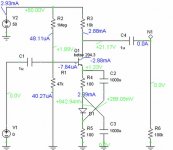
I attached a linearizion idea circuit which is a bit similar to Xquad,
o found this somewhere on the net...
Attachments
I never saw any saturation with the plain quad.
Then again, I have that active tail thing goin on...
Keeps the quesscent roughly equal all times.
.
Raw xquad is working better in this instance than
Evaquad or Evaquad wth driver collectors parrallel.
I'm also driving an emitter drop to the rail, which
isn't a huge voltage swing on the collector.
Then again, I have that active tail thing goin on...
Keeps the quesscent roughly equal all times.
.
Raw xquad is working better in this instance than
Evaquad or Evaquad wth driver collectors parrallel.
I'm also driving an emitter drop to the rail, which
isn't a huge voltage swing on the collector.
Last edited:
Where is the problem, cause I'm just not seeing it.
No transistor of this quad loses collector voltage,
even in moderate clipping, its all good...
The two waves in the center (blue maybe little hard
to see) are actually all four voltages of the xquad.
The left and right closely overlap, both sides look
as-if transistors bias like diodes. Differential currents
vary, but differential voltages are held nearly equal.
Its definitely doing something though, distortion is
unmistakably reduced by presence of the xquad.
No collectors here ever dip below the base voltage.
I have no idea what is this "phase reversal" you say
when the collector saturates. Do you simply mean the
quad would stop reversing things working as a quad?
Saturated behavior would revert to normal LTP ???
I don't think this tail allows the latched condition to
exist. Even if you hit it with a transient huge enough
to make one transistor saturate, and phase revert to
uncrossed LTP. It would quickly be put back to right.
Attachments

Last edited:
If it is included in an amplifier having global NF, this will be implicitly realized.
do you have the idea hot to prevent this circuit from the saturation?
At least under normal working conditions.
But to prevent a latch-up during some freak event, there has to be some form of safety net, it would be suicidal to leave the circuit do whatever it wants, that's the reason for the diode clipper at the input.
But when a larger dynamic is required, as in the Tringlinator, a solution is to increase the Vbe of the lower transistors, by means of resistors or zeners f.e.
If you look attentively at the schematic, you will see that that's what is done there.
Incidently, it leaves more Vce space to breathe for the transistors.
It is the poor relation of the Xquad then.I attached a linearizion idea circuit which is a bit similar to Xquad,
o found this somewhere on the net...
It simply mimics the effect of a LTP, but with a diode to replace the other transistor.
The compensating effect is already crude in a LTP, it is equivalent to assume that exp(-k*V)=-exp(k*V), but with two heavily dissimilar components, it will be worse.
The only advantage that I can see in this circuit is the fact that the bias current is recycled, thus halving the current consumption compared to a LTP.
But it costs two big e-lytics, and a similar trick could be used with transistors.
Not of a great practical value.
No that's what I explained in my previous post, the NFB keeps the input voltage <0.6V.Where is the problem, cause I'm just not seeing it.
No transistor of this quad loses collector voltage,
even in moderate clipping, its all good...
That's in sim. With a real circuit, you have 99% chances the circuit locks up as soon as it is powered.
I know, I've been there.
In the sim try to put an .ic V(base of Q2)=2v, I think it will latch up.
Yes, exactly.No collectors here ever dip below the base voltage.
I have no idea what is this "phase reversal" you say
when the collector saturates. Do you simply mean the
quad would stop reversing things working as a quad?
Saturated behavior would revert to normal LTP ???
Dunno, try the .ic experiment to find out.I don't think this tail allows the latched condition to
exist. Even if you hit it with a transient huge enough
to make one transistor saturate, and phase revert to
uncrossed LTP. It would quickly be put back to right.
- Home
- Amplifiers
- Solid State
- ♫♪ My little cheap Circlophone© ♫♪