Hi
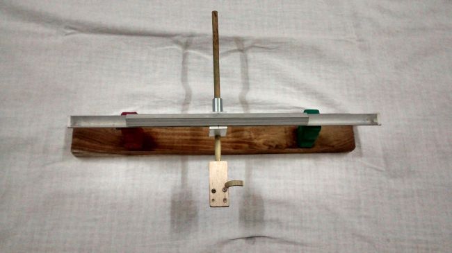
I'll take some close ups later on-very easy to make. Arm wand in total is 160mm with around 60mm from pivot to stylus.
Regards
Chris
I'll take some close ups later on-very easy to make. Arm wand in total is 160mm with around 60mm from pivot to stylus.
Regards
Chris
Hi
The tubes are 6mm aluminium. Top tubes are also 6mm but carbon fibre- I just had it lying around. How does it perform? Flawlessly. I had continual problems using ball races but with this, it has tracked everything I've thrown at it with no problems. And I have a few more improvements up my sleeve-when I get the free time of course!
Chris
Chris... Is the CF tubing thick walled, or a rod? I am considering a similar top carriage as I believe the low weight is important. Is it quite smooth?
Yours has a nice clan aesthetic to it, and allows me to see what's going on, but I'm looking forward to more pics. The lifter is a beauty 😉
Anyone tried a single top carriage? I saw someone mention a larger diameter tube, cut in half, riding atop the balls... Did that ever get explored?
I believe a better option would be to replace the small piece of iron with a magnet and use magnetic repulsion instead with the magnetic strip being below the arm tube.
Niffy
My experience mirrors Niffy's, that magnetic repulsion works better than attraction.
I recommend a pivoted see-saw that extends across the entire width of the tonearm rails, with an upward-facing magnetic strip mounted under the tonearm tail stub (on the near side of the see-saw), and an adjustable counterweight on the far side of the see-saw. The tonearm tail stub is fitted with a low-mass magnet of opposing polarity to the magnetic strip on the see-saw.
The repulsion between tonearm tail stub and magnetic strip rocks the see-saw up and down, and moving the counterweight in and out enables the VTF to be altered.
Combining magnetic repulsion with a pivoted and counterweighted see-saw results in a self-adjusting system regarding the spacing between tonearm and see-saw - the gap stays quite uniform regardless of whether the LP is flat or warped (unlike magnetic attraction).
By driving the counterweight indirectly via magnets and pivoted see-saw rather than directly from the tonearm stub, a counterweight that only swings up and down rather than moving side-to-side can still apply uniform VTF across the entire LP.
It is possible to exchange or supplement the counterweight with a spring system if dynamic rather than static balancing is desired.
kind regards, jonathan
Anyone tried a single top carriage? I saw someone mention a larger diameter tube, cut in half, riding atop the balls... Did that ever get explored?
just a speculation but I think there is not much to gain, in the arm with two rods the weight can be very low if you use hollow tubes with not too large diameter, I didn't use a headshell and that saves a lot of weight, I think the half tubing needs to be very well chosen as to allow a nice fit and not let the carriage "wiggle" and it will have to be very smooth, I dont know how easy it would be to get this component, see the diagram :

carriage with two rods , its got only two contact points or four in total if you consider the lower support:

a variation could be a "straight" upper carriage made with a "L" shape bar:

a simplification of the "Percy Wilson" from post #11:

in this case you also keep two contact points (four in total).
The Soyuz Linear Tracking Arm - Yet Another Version.
I got this design from an old British Radio and Electronics magazine from the early 1960s that has been in my possession for good number of years now. I found that the basic design and concept was similar to Soyuz's brilliant design and also to the Percy Wilson design - the same two rail and two ball and four contact points design was used here. Though this design appeared to be more stable as far as the run-away balls were concerned. Lack of time and availability of the correct size of vee-channel and ball bearings prevented me from trying out this design earlier. I had to use whatever size that I managed to procure locally. Finding the right size of ball bearing, too, took a long time. The validation of the design was carried out a couple of days back and I am reporting my findings so far. Soyuz's latest post #123 provided the impetus for me to post and share this version of his LT arm design.
There are no changes to the basic design and only the lower and upper rails were replaced with lengths of aluminium 90° vee-channel or angle in place of the tubes that were used so far in the Soyuz design.
The components –
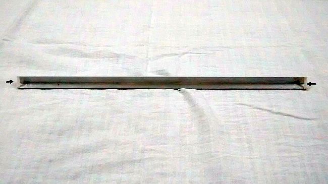
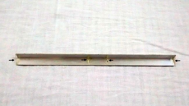
The lower rail had two stops glued to the ends to prevent the ball bearings from escaping from the open ends. The upper rail was divided into three sections by gluing pieces of triangular stops to ensure that the movement of the balls remained within the limits. Like so -
bgruhn had made an observation about limiting the balls' travel in his post #61. The original constructor of this design had used these stops in his design. Fifty years on Jezz-the-Fezz also suggested as much in Post #11 Para 2.
Hmmm, something about great minds thinking alike.....? 😀
This is a frontal view of what I constructed for validation of the design. The gap between the upper and lower rail can be seen quite clearly.
Another view -
More details and images to follow soon.
I got this design from an old British Radio and Electronics magazine from the early 1960s that has been in my possession for good number of years now. I found that the basic design and concept was similar to Soyuz's brilliant design and also to the Percy Wilson design - the same two rail and two ball and four contact points design was used here. Though this design appeared to be more stable as far as the run-away balls were concerned. Lack of time and availability of the correct size of vee-channel and ball bearings prevented me from trying out this design earlier. I had to use whatever size that I managed to procure locally. Finding the right size of ball bearing, too, took a long time. The validation of the design was carried out a couple of days back and I am reporting my findings so far. Soyuz's latest post #123 provided the impetus for me to post and share this version of his LT arm design.
There are no changes to the basic design and only the lower and upper rails were replaced with lengths of aluminium 90° vee-channel or angle in place of the tubes that were used so far in the Soyuz design.
The components –

The lower rail had two stops glued to the ends to prevent the ball bearings from escaping from the open ends. The upper rail was divided into three sections by gluing pieces of triangular stops to ensure that the movement of the balls remained within the limits. Like so -


bgruhn had made an observation about limiting the balls' travel in his post #61. The original constructor of this design had used these stops in his design. Fifty years on Jezz-the-Fezz also suggested as much in Post #11 Para 2.
Hmmm, something about great minds thinking alike.....? 😀
This is a frontal view of what I constructed for validation of the design. The gap between the upper and lower rail can be seen quite clearly.

Another view -

More details and images to follow soon.
Lift/Lower Device
Hi Mortron
As promised. The carbon fibre tubing is some I had lying around. Very smooth surface and works a treat. I don't believe weight is a particular problem with this design as long as you don't go overboard.
Hi Mortron
As promised. The carbon fibre tubing is some I had lying around. Very smooth surface and works a treat. I don't believe weight is a particular problem with this design as long as you don't go overboard.
Attachments


Super clear pics Chris, thanks for that🙂
Build thoughts are now going thro' my head to see what I can do from the garage
GC
Build thoughts are now going thro' my head to see what I can do from the garage
GC
To Muziklava-What size is the v-channel and what size bearings do you use?
Thanks
Chris
Hi Chris,
½” x ½” (12.7 mm x 12.7 mm) size vee-channel
0.438” (11.15 mm) size ball bearings.
This gives a clearance of ~ 2 mm between the upper and lower rails. You can use standard 11 mm size ball bearings. I used what was available.
The lengths of the rails –
Upper Rail – 200 mm
Lower Rail – 350 mm
Actually, I used the same lengths as you did and added a bit more as a safety net, just in case. 😀
Regards,
ML
Ball distance
Hi Guys,
A question for anyone who has tested one of the above please - Is there an 'optimum' distance between the balls at set-up?
Just getting the necessary bits together before I start🙂
Cheers
GC
Hi Guys,
A question for anyone who has tested one of the above please - Is there an 'optimum' distance between the balls at set-up?
Just getting the necessary bits together before I start🙂
Cheers
GC
An Apology
The telephone/internet service in our area got disrupted since noon of 29th May and I've been offline since then. I've learnt that some road repair workers accidentally damaged the underground telephone/internet cable connecting our area. It appears that it will take some more time for the services to be restored.
I've now borrowed a mobile 3G internet device and I hope to post the remaining part of the Validation build by this evening. I apologize for my silence so far.
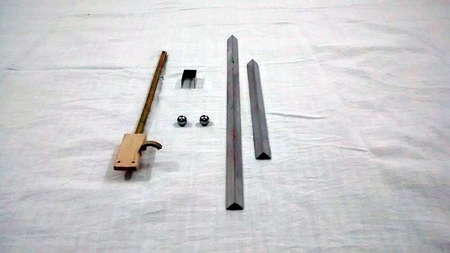
The Soyuz Linear Tracking Arm - Yet Another Version (Cont'd)
The construction of the rails and the bracket was done accurately for conducting trials while the tonearm ( headshell, wand and counterweight) is a mock-up made for the measurements.
The Materials:
For the Rails -
½” x ½” (12.7 mm x 12.7 mm) size aluminium v-channel or angle
Upper rail - 200 mm
Lower rail - 350 mm
The V-channels I used had only 0.5 mm thickness and felt quite fragile when handled so I cut two lengths of each rail and glued them together with Araldite for strength and rigidity. Allow about 24 hours for the Araldite to set.
Weight of the Upper Rail = 12 grams
The Upper rail was divided into three sections as shown in the third photograph in my first post. Four triangular stops were cut to the size of the channel and glued to it. Any thin, hard material like plastic or hardboard can be used. A pair of tweezers becomes quite handy here.
The measurements for the sections in my validation model were -
Left and Right sections - 3½" (89 mm) each
Middle section - ¾" (19 mm)
Note: The size of the Middle section can be made according to the width of the bracket used if one so desires. I have deliberately erred in favour of safety by using slightly larger measurements.
Two pieces of plastic tube were cut and glued to the ends of the Lower rail. This is to prevent the ball from escaping as well as to act as stops for the Upper rail. In any case the second use is not critical because the stops in the Upper rail serve the same purpose too.
Ball bearings - 11.15 mm diameter. Standard 11 mm diameter balls can also be used, if available
Weight per ball bearing = 5.6 grams
The Bracket was made out of a piece of aluminium and weighed ~ 2.4 grams
The Tonearm is a mock-up though made to actual dimensions. An old Shure 44-4 cartridge and stylus was used. Only the fitting, perhaps, may not be as accurate as desired. I only wanted this section for measurements and weight.
Weight of the headshell + cart + wand + CW = 26.2 grams
Total weight of Carriage = 51.8 grams
Weight is not a criteria for the Validation phase but I have left ample scope for weight reduction. The ideal weight for the entire carriage should be about 42.5 grams including the weight of the ball bearings.
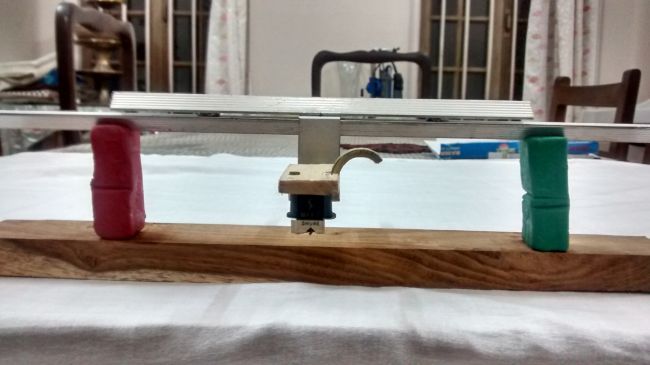
The support for the Validation build are two blocks of Plasticine. Yes, those hideous red and green coloured ones. Quite convenient for setting up height and correcting the levels of the X and Y axes though! 😀
The construction of the rails and the bracket was done accurately for conducting trials while the tonearm ( headshell, wand and counterweight) is a mock-up made for the measurements.
The Materials:
For the Rails -
½” x ½” (12.7 mm x 12.7 mm) size aluminium v-channel or angle
Upper rail - 200 mm
Lower rail - 350 mm
The V-channels I used had only 0.5 mm thickness and felt quite fragile when handled so I cut two lengths of each rail and glued them together with Araldite for strength and rigidity. Allow about 24 hours for the Araldite to set.
Weight of the Upper Rail = 12 grams
The Upper rail was divided into three sections as shown in the third photograph in my first post. Four triangular stops were cut to the size of the channel and glued to it. Any thin, hard material like plastic or hardboard can be used. A pair of tweezers becomes quite handy here.
The measurements for the sections in my validation model were -
Left and Right sections - 3½" (89 mm) each
Middle section - ¾" (19 mm)
Note: The size of the Middle section can be made according to the width of the bracket used if one so desires. I have deliberately erred in favour of safety by using slightly larger measurements.
Two pieces of plastic tube were cut and glued to the ends of the Lower rail. This is to prevent the ball from escaping as well as to act as stops for the Upper rail. In any case the second use is not critical because the stops in the Upper rail serve the same purpose too.
Ball bearings - 11.15 mm diameter. Standard 11 mm diameter balls can also be used, if available
Weight per ball bearing = 5.6 grams
The Bracket was made out of a piece of aluminium and weighed ~ 2.4 grams
The Tonearm is a mock-up though made to actual dimensions. An old Shure 44-4 cartridge and stylus was used. Only the fitting, perhaps, may not be as accurate as desired. I only wanted this section for measurements and weight.
Weight of the headshell + cart + wand + CW = 26.2 grams
Total weight of Carriage = 51.8 grams
Weight is not a criteria for the Validation phase but I have left ample scope for weight reduction. The ideal weight for the entire carriage should be about 42.5 grams including the weight of the ball bearings.
The support for the Validation build are two blocks of Plasticine. Yes, those hideous red and green coloured ones. Quite convenient for setting up height and correcting the levels of the X and Y axes though! 😀
Hi Brassnwood
Just measured the distance-4" gives enough travel for the carriage to traverse the record and remain stable on my arm. If you need further details please let me know. It's a real cracker-as Frank Carson used to say.
By the way, until this weekend I'd been using an old VMS20E with 'special' stylus that I bought years ago. Didn't want any expensive accidents before I was happy with things. Changed it yesterday for an Ortofon MC15 Super I had lying around-what a difference it made!! This is so superior to two parallel trackers I've had in the past-the Opus 3 Cantus and a Clearaudio Tangent (very expensive and very over-rated in my experience.
Regards
Chris
I realise I didn't put a heading on my last comments. As you will have no doubt gathered, I'm describing the distance between the two ball bearings!
Chris
Chris
Thanks Chris,
I will use that as a starter for 10😉
You remember Frank Carson do you? .. 😱
Cheers,
GC
I will use that as a starter for 10😉
You remember Frank Carson do you? .. 😱
Cheers,
GC
Frank C
I think we will leave it there, thanks Chris.
Sorry but another question for all you experts ....
Which is the best 'Compromise' ?
1. The pivot, level with the stylus tip & a long arm
... or ....
2. Short arm but the Stylus way below the pivot????
Some help here please before I decide which way to go😀
Many thanks
GC
- Home
- Source & Line
- Analogue Source
- My Linear Tracker (a new variation perhaps?)