Any thoughts on that claimed slew rate ? It just doesn't seem possible to me on a number of counts. Designing for slew rates approaching even half the claimed figure is a monumental exercise. Is the slew rate "symmetrical" I wonder ie same positive as negative going ?
No one remember the old Maplin amp -- still good today.
No one remember the old Maplin amp -- still good today.
Attachments
djk said:"I have suggested that the rail fuse rating be selected to pass about half the peak output current into the specified load. "
Which is what I mentioned:
"With ± fuses, the RMS speaker current may be 1.414 times the rail fuse rating "
Each rail current is exactly SQR(2)/3.14 times the RMS current in the speaker/load, or about 0.45. Which means the RMS load current may be about 2.2 times the rail fuse rating (assuming a resistive load).
This is very close to Quasi's recommendation.syn08 said:
Each rail current is exactly SQR(2)/3.14 times the RMS current in the speaker/load, or about 0.45. Which means the RMS load current may be about 2.2 times the rail fuse rating (assuming a resistive load).
AndrewT said:
It's not Rds on that is the limiting factor.
It's the gate drive voltage which needs an overhead of between 5V and 8V when delivering maximum power.
Actually no, it's Rds_on because with it being a fairly high value at approx 1.2 ohms, when passing current this creates a voltage drop from drain to source by simple ohms law, which at currents of several amps forces the source to be several volts below the gate which is swung close to the rails (drain) by the driving stage.
It is for this reason that higher voltage driver rails make little to no difference to overall swing when driving high currents with these type of output devices.
you're making me think again.richie00boy said:
Actually no, it's Rds_on because with it being a fairly high value at approx 1.2 ohms, when passing current this creates a voltage drop from drain to source by simple ohms law, which at currents of several amps forces the source to be several volts below the gate which is swung close to the rails (drain) by the driving stage.
It is for this reason that higher voltage driver rails make little to no difference to overall swing when driving high currents with these type of output devices.
Not good for my brain cells. Will it hurt?
EDIT: how come RDS_on is 1.2 ohms? Current Hexfets like the IRFP240 have 0.2 ohms at 12A and I wouldn't expect that it changes so much when cutting the current by half.
Thanks for the information. I really was not aware that these parts perform that poor. 10 seconds at 200%. Wow.
Have fun, Hannes
As we can see, a 6A fast acting fuse will open up in less than 10 seconds at 200% of rated current.
Thanks for the information. I really was not aware that these parts perform that poor. 10 seconds at 200%. Wow.
Have fun, Hannes
h_a said:EDIT: how come RDS_on is 1.2 ohms? Current Hexfets like the IRFP240 have 0.2 ohms at 12A and I wouldn't expect that it changes so much when cutting the current by half.
These are 2SK1058/2SJ162 lateral MOSFETs. According to the datasheet they have a VDS(sat) of 12V at ID=7A and VGD=0 (an ugly way to spec Rds...) which renders Rds(sat)=12/7=1.4ohm.
Now, this is at the saturation limit (VGD=0). At small VDS, Rds is about half, or 0.7ohm.
Two devices in parallel will of course have 0.35ohm.
on the other hand
Fuses an fuse ratings should be not the problem .
In the previous posts there is a lot of power and stability issues.
Simular troubles you may find looking at posts related to legend 4 amplifier .
Of course this looks like a far more advanced design but overestimated like legend i think .
But ...thats just a personal opinion ( from some one that uses or abuses amplifiers in small pa application )
- Status
- This old topic is closed. If you want to reopen this topic, contact a moderator using the "Report Post" button.
- Home
- Amplifiers
- Solid State
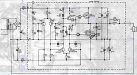
- My latest project - fantastic power amp "Sigma"