Hello SMPS builders
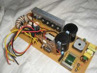
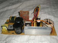
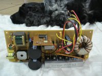
This is my last switchmode power supply. I build it with 2 inches toroidal transformer, half bridge topology, 4 IGBT output, optozener regulated (+43/-43VDC), if regulated less it work in +66/-66VDC. SG3525 PWM controller transformer direct drive, buffer less, now, to wait a new-next power amplifier.
Comments are wellcome.
Attachments
very interesting
this is to drive amplifier of how many watts ????
caus ei amreally interested also schematics will be very nice
on the other hand may be is allready on production and it is for sale ???
in this case i am also interested
east_electronics@yahoo.gr
sakis
this is to drive amplifier of how many watts ????
caus ei amreally interested also schematics will be very nice
on the other hand may be is allready on production and it is for sale ???
in this case i am also interested
east_electronics@yahoo.gr
sakis
Hey
Take a look here!
http://i186.photobucket.com/albums/x186/chacalpowers/SMPSPA.jpg
http://i186.photobucket.com/albums/x186/chacalpowers/SMPSPA2.jpg
http://i186.photobucket.com/albums/x186/chacalpowers/SMPSPA1.jpg
http://i186.photobucket.com/albums/x186/chacalpowers/PWMCNTRLR.jpg
http://i186.photobucket.com/albums/x186/chacalpowers/NEXTBIG1.jpg
http://i186.photobucket.com/albums/x186/chacalpowers/HEATSINK.jpg
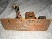
As an ex SMPS designer I was tempted to say same but didnt but now I will. Needs at least 8 mm creepage and clearance between input and output (including across opto / isolation barrier and any swtiching XFR) and 4mm or more betwen L and N / L and E. Of course if its for private use you can do as you wish but if you are 'advertising' the design then I would strongly suggest putting a warning on it to protect yourself. regards A Streeter
- Status
- This old topic is closed. If you want to reopen this topic, contact a moderator using the "Report Post" button.
- Home
- Amplifiers
- Solid State
- My Last Smps Project