Hi Cortez,
I bought all my caps from these three sites.
http://www.hndme.com/storecapelectrolnichFG.html
http://www.digikey.com/
http://www.audience-av.com/passive.htm
I bought all my caps from these three sites.
http://www.hndme.com/storecapelectrolnichFG.html
http://www.digikey.com/
http://www.audience-av.com/passive.htm
Leolabs said:Hi,AAK.Have you try to add a emitter follower before the VAS???
Or use this emitter follower to drive the emitter of the VAS that is used as a common base amplifier thus reducing miller effect? Of course there is no phase change for CB compared to CE, so the mirror is reversed in the LTP...no big changes. Less miller compensation is always better, if you can still maintain stability.
Thx, and the resistors ? Are they VishayDale military types ?AAK said:I bought all my caps from these three sites.
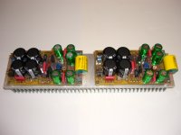
Here's a pic of two new prototypes boards on one heat sink. All I need now is to order some professionally made boards to complete my 8 channel home theater amp. Know I could place all of them in one enclosure, but that would make one heavy mother, so most likely I'll divide it into two 4 channel amps. For those that have expressed interest in some boards I'll be contacting you as soon as they arrive.
The amp in the pic is the same as the original boards, accept I added about 0.4" to the board length to accommodate for two more power supply caps. This way you can increase the capacitance to 10000uF per rail when using +/-50V rails.
The amp in the pic is the same as the original boards, accept I added about 0.4" to the board length to accommodate for two more power supply caps. This way you can increase the capacitance to 10000uF per rail when using +/-50V rails.
Attachments
hi AAK,
These are looking very good.
I like the idea of PSU to the left of the output transisitors and amp circuitry on the right.
How do you mount the output transisitors to the heatsink? Do you do it before soldering to the PCB or are there holes that I can't see?
Also, having separate PSU for hi quality audio is a good idea but are you going to have separate PSUs for all 8 channels?
I've seen lots of people mount amps like this on the heatsink. Is there any problems having the PCB so close to warm heatsinks? I imagine you are running them with relative low bias to keep things from getting too hot.
How many transformers are you going to use?
Good luck
Hi Greg,
Thanks for the complements. There is no mounting holes on the PCB, the transistors are first mounted to the heatsink then soldered to the board.
<<Also, having separate PSU for hi quality audio is a good idea but are you going to have separate PSUs for all 8 channels?>>
Yep, 8 mono channels.
<<I've seen lots of people mount amps like this on the heatsink. Is there any problems having the PCB so close to warm heatsinks? I imagine you are running them with relative low bias to keep things from getting too hot.>>
No problems. The spacing between the board and the heatsink is 0.5". The bias is set to about 25ma.
<<How many transformers are you going to use?>>
I'm actually going to use four transformers, each having mono dual secondary windings. If you go to my website you can see the transformer under hybrid amplifier. I have 25 of of these transformers, so I figure I might as well use them.
Hi Al,
Interesting design you have. I have a couple quick questions:
1) Have you run this amp using lower rails? I have a 15-0-15 RMS 225VA, 20-0-20 RMS 225VA and 25-025 RMS 225VA toroid.
2) If one was to use lower rail voltage what, if any, changes in resistor values might be required? If there are changes required I have a preference to knowing the formula used to determine the value.
3) What ballpark rail loss does the design have? I am not as familar with BiPolar losses. I am not a amp expert, but so far I have learned there is about a 12V RMS drop from the Toroid rating.
4) If I understand correctly you feel the schematic from Post #2 sounds better than from Post #37. Correct?
Regards,
John L. Males
Willowdale, Ontario
Canada
25 April 2006 19:12
Hi John,
15-0-15RMS is about +/-22V rails. The amp should work at these voltages, but it will involve changing some resistor values. I'll simulate it, then test it on an actual board, and get back to you. I figure sometime next week.
I measured about 8V RMS drop.
I've not compared the two amps, but when I do I'll post the results.
Here are some THD measurements of the 100 watt version.
Into 8ohm @ 1khz
50 watts: THD = 0.008%
100 watts: THD = 0.01%
Into 4 ohms @ 1khz
100 watts: THD = 0.01%
150 watts: THD = 0.017%
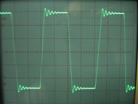
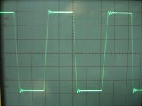
Here's a pic of a square wave into 8||4.7uF at 10Vrms @ 10khz without
using an R||L on the ouput.
Into 8ohm @ 1khz
50 watts: THD = 0.008%
100 watts: THD = 0.01%
Into 4 ohms @ 1khz
100 watts: THD = 0.01%
150 watts: THD = 0.017%
Here's a pic of a square wave into 8||4.7uF at 10Vrms @ 10khz without
using an R||L on the ouput.
Attachments
Eva said:[snip] It seems like none of you has actually tried a single pair of output devices with increasing rails and decreasing loads in order to get a real reliability reference.
However, there are humble people with little budget like me that enjoy these tests. According to my experience, I would regard a pair of 2SC5200 and 2SA1943 as more than reliable with +-50V rails for music signals. Even at 4 ohms, a -6dB square wave or a sine into a plain capacitor would be required to reach thermal damage or secondary breakdown.
Just as a reference, these are some setups that I was absolutely unable to blow with music signals:
- A single pair of TIP35C/TIP36C with +-45V regulated rails, using a CFP Vbe multiplier to set bias properly and a 4 ohm reactive load (+/-45 degrees). The special Vbe multiplier is required because these transistors feature lower than usual Vbe and higher temperature coefficient.
[snip]
Assume proper heatsinking and cooling in all cases.
Eva said:
A square wave at -6dB (an amplitude of 50% rail voltage) yields the worst-case absolute maximum amplifier dissipation when driving any resistive load (the output stage dissipates as much power as it outputs).
Hi Eva,
If I may offer a few observations and ask a few questions with regards to some of the above points.
I happen to be lucky and discovered a gem of a commerical receiver that uses a toroid and has a single pair of 2SA1943/2SC5200 output devices with the 2SD669A and 2SD649A drivers all mounted on the heatsink. The 2SD669A and 2SD649A are mounted close together side by side with the 2SA1943 and 2SC5200 about 1/2 inch on each side of the medium driver pair. I cannot see any Vbe device mounted on the heatsink. For $80.00 Canadian, relays at the PSU and speaker outputs, binding posts for speakers and preamp to amp RCA with jumper connectors I pick it up to hold me over. I have been trying for some time with various time demands in way to build my amps to replace a 1970's amp showing its age and design for some time now. I have used this new receiver for about a month now. I believe the components are "burned" in now as the initial sound was above average and now seems much more detailed the past week or so.
I just happened to discover this thread a few days ago. I wanted to follow up on the -6dB test you had posted.
Based on your comments of -6 dB square or sine wave test I wanted to try a quick test rather than set up test equipment to test. So the test I did is your suggested test, but informal with speakers connected. Using a test CD I have had for years and HP973A I played the 30 second 40Hz db referenced to CD signal. I started at about the "40" level of the digital volume control that has a range of 0 to 74. The unit displays dB when the volume is changed, but I have no idea as yet the gain of the amplifier nor the stepping increments of the volume control, but I know the default "20" for the volume it powers up with is very low. I then tried to volume at "45" a few times and there was an odd drop out and relay like sound for moment then the sound returned during the 30 second sample. I tried again and no problems. I tried at volume setting "50" and the amp relays click and sound stopped about 10 seconds in, then about 10 seonds later the sound started again just for 2 seconds or so and stopped again, all with relay clicking noises. I found the amp to be warm to touch, but could not touch the heatsinks as the case cover was on. I coudl feel the heat of the rising air as well above the heatsing area. Until now, even when I played the amp with classical or soft pop music it always ran cool with no rising heated air, and never above a "40" volume setting as rule and usually about the "35" volume setting. I run the amp at "60" for DVD but the signal source is via some front end electronics that happens to lower the signal compared to the usual signal level of a DVD.
I then when back to "40" and played the 30 second 40Hz signal about 5 times and besides the amp being warm and rising warm air above the heatsinks there was no cut out. I raised to "48" volume and found cut out happened a few short moments of the 30 second signal I tried just once. I then did the "45" volume setting about 8 times with no drop out of the protection circuits. The "45" volume level test showed just tad over 8VAC RMS on the speaker terminals of the amp with the HP973A. I had actually measured the DC of the amp a few days earlier and was 0.027VDC for left and 0.026VDC for right at no source signal. Tad high I suppose, bit for the type and commerical consumer of unit designed I assume this is reasonable?
The amp was still warm and rising air heat after what was about 30 minutes of this testing overall at the noted volume levels above and a few other levels > 40 and < 48 before I settled in on the "45" level test. It took > 30 minutes < 45 minutes for the amp to cool down to the usual no heat level I have been used to using the amp while playing music on it after the 40Hz test at the usual "35" volume setting for the past month.
My question would be based on the "45" volume test I did and the frequent cut out of protection circuit(s) of this amp at the "48" and "50" volume would you tend to think this amp behaved as expected for the -6dB test you had suggested? I have no schematic of the receiver and do not know the secondary rating of the toroid nor its VA rating, nor the nature of the protection circuit(s) or relays. I have had no success as yet to obtain the schematic. My best guess is the toroid is likely to be at least 250VA, might be 300VA at best. The amp is rated at 100W for each channel, but not stated if this is RMS or some form of music power.
Would it be correct to assume this test would be a -6dB test based on the maximum volume setting being 74 and the likely recactive element of the passive 3way speakers the amp was driving? If this is like the -6dB test you suggested do you feel this receiver behaved as expected in the general sense? Would it be correct to assume these output devices are likely genuine from the test results of this test? I am asking not to validate my purchase of this amp, but in the context of the test I did. This test might be helpful in my future ability to test is power BiPolar devices I am not sure about after trying the capactive testing you have suggested in a different thread. The fact it so happens to be a single pair of output devices are the Toshiba 2SA1943/2SA5200 that the amp of this thread is designed for is bonus.
Your answers/comments would enable me to develop a feel for both the -6dB test you suggested (for any amplifier BiPolar, MOSFET, darlington, maybe tubes as well), validate various circuit/protection/heatsinking/thermal insulation/PSU elements of a design, and the general nature of these Toshiba output devices behaviour for this test.
Regards,
John L. Males
Willowdale, Ontario
Canada
27 April 2006 14:56
I am also curious to know if you have posted the A single pair of TIP35C/TIP36C design with the special Vbe you mentioned was used anywhere?
Hi,
I think the symptoms you are hearing are normal for a well protected output stage.
Sounds like you have a temperature sensor on the heatsink that cuts the output until it cools again.
A disadvantage of this system is that you get heat cycling of the output stage and the fatigue life of the semis is considerably shortened if this is repeated regularly.
Also sounds like the heatsink is very small and only suitable for domestic use.
Your 8Vac (about 8w into 8ohms) is about -11db relative to a maximum of 100W. This is a gentle test on 8ohm speakers, or were yours 4ohms speakers.
It is normal to test into a test load. You can tap off this test load an attenuated signal that you can feed into another amp and speaker so you can hear what you are measuring. For the sake of your ears and your family I suggest you don't test into your speakers. It might save the speakers from harm as well if the amp were to fail while being tested.
- Status
- This old topic is closed. If you want to reopen this topic, contact a moderator using the "Report Post" button.
- Home
- Amplifiers
- Solid State
- My Killer Little Amp