As far as I know, the 2N4091/PN4091/MMBF4091 are the same transistor die in different packages. The 2N4391/PN4391/MMBF4391 are near-equivalents.anybody know if the PN4091 is a good substitute for the 2N4091?
Dale
As far as I know, the 2N4091/PN4091/MMBF4091 are the same transistor die in different packages. The 2N4391/PN4391/MMBF4391 are near-equivalents.
Dale
awesome, thanks!
EDN had an article a while ago on an ultra pure sine wave oscillator to test 18 bit ADC's. Would this be useful?
As far as I know, the 2N4091/PN4091/MMBF4091 are the same transistor die in different packages. The 2N4391/PN4391/MMBF4391 are near-equivalents.
Dale
awesome, thanks!
A while ago there was an article about an ultra pure sine wave oscillator. Any thoughts about its application in the distortion analyzer?
Would this be useful?
Not really. Designing a fixed audio frequency, slow settling oscillator with harmonics below -110 dB is not that difficult; things start to get interesting if you want a wide frequency range and/or fast settling at low frequencies.
Samuel
Not really. Designing a fixed audio frequency, slow settling oscillator with harmonics below -110 dB is not that difficult; things start to get interesting if you want a wide frequency range and/or fast settling at low frequencies.
Samuel
hmm. ok, thanks.
I think there should be a careful investigation into the capabilities and limitations of the Silonex optocouplers as gain control elements. There are a couple of threads about that article here on the Forum, as well as several discussions of Jim Williams' previous effort - a fixed-frequency oscillator with supposedly unmeasurable distortion levels. Seed this Forum's search engine with "Jim Williams oscillator" as a starting point.A while ago there was an article about an ultra pure sine wave oscillator. Any thoughts about its application in the distortion analyzer?
Currently active projects along this line that I'm aware of include:
- "Ultra Low Distortion State Variable Oscillator" at < http://users.picknowl.com.au/~glenk/uldo.htm >
- "Make Your Heath IG-18 into a Super Audio Generator" at < http://www.tronola.com/html/ig-18_mods.html >
- Several efforts described on various pages at Dick Moore's site, < http://www.moorepage.net/ >.
I believe you put significant effort into understanding those problems. Would you be willing to share your thoughts (even a handful of 2-line bullet points) on the most promising approaches and design features? Did you publish a final schematic for the sample-hold/track-hold amplitude detector?. . . Designing a fixed audio frequency, slow settling oscillator with harmonics below -110 dB is not that difficult; things start to get interesting if you want a wide frequency range and/or fast settling at low frequencies.
Dale
Low distortion oscillators
Hi Guys,
Ultra low distortion oscillators have always held my attention as a design challenge. So far I have not found anything better than a state variable oscillator, but there are probably approaches that I have not tried.
Last summer I spent some time investigating the THD-measuring limitations of my THD analyzer. I had a couple of findings which may be of interest, but which people should use caution in generalizing.
First, although we all spend a lot of time on the issue of ripple in the AGC detector circuit, I did not find this to be the limit in my unit. Recall that my unit uses just a well-balaced full-wave rectifier with speed-up diodes that act to speed up settling. No multi-phase amplitude detection, no sample-hold, etc.
Rather, what i found was the importance of the distortion introduced by the agc element, namely the JFET variable resistor in my case. I found that it is valuable to trim the feedback ratio to the gate, as the generally-accepted value of 0.5 is not always optimal.
Another important point for oscillators in a THD analyzer application is phase noise and amplitude noise. This is currently the ultimate limit in my analyzer, although I did not track it down to the oscillator vs the state variable notch filter. Phase noise or oscillator noise interferes with perfect nulling in the state variable notch filter. This can be seen by feeding the residual into a spectrum analyzer. It "looks" like the fundamental is not fully nulled, but in reality it is perfectly nulled on the average, but phase noise and/or amplitude noise interferes with a uniformly perfect null over time.
I did not discover that other op amps besides the 5534 devices improved matters, but more work probably should have been done.
Cheers,
Bob
Would you be willing to share your thoughts on the most promising approaches and design features?
I'm happy to provide guidlines and specific hints, however we need clear design goals. Things get exponentionally more difficult with tighter specs, so we need to know how far we aim:
* What is the desired frequency range?
* What is the desired harmonic distortion level?
* What settling time is acceptable?
* Does the oscillator also need low wideband and sideband noise, not just low harmonics (i.e. also optimised for THD+N)?
Samuel
Last edited:
* 10Hz to 100kHz, willing to compromise by a decade each end
* -140dB, preferrably -160dB
* say < 1 minutes
* I guess THD+N, since noise will later mask the THD measurements
Demanding specs, I know ....
Patrick
* -140dB, preferrably -160dB
* say < 1 minutes
* I guess THD+N, since noise will later mask the THD measurements
Demanding specs, I know ....
Patrick
* 10Hz to 100kHz, willing to compromise by a decade each end
* -140dB, preferrably -160dB
* say < 1 minutes
* I guess THD+N, since noise will later mask the THD measurements
Demanding specs, I know ....
Patrick
My 2 cents on this, do this with a high end sound card... and related SW
Hp
Let's start with a Krohn-Hite 4402 and improve the (noise + distortion) by 20 dB or so. Proposed design requirements & desired goals:
Dale
p.s. - Yes, I know the dB and volt units don't agree perfectly. We can quibble over the last digit of the values at a later time.
- Signal frequency range: 10 Hz to 100 KHz minimum (200 KHz goal)
- Output level: 5.0 V (RMS) /+16 dBm into 600 ohm load
- Total corruption (harmonics, noise, hum, ripple, etc - measurement bandwidth greater of 30 KHz or 10 times signal frequency - output level 2.5 V (RMS) into 600 ohms):
- -130 dB ( -140 dB goal), 30 Hz - 10 KHz
- -120 dB ( -130 dB goal), 10 Hz - 30 Hz and 10 KHz - 30 KHz
- Settling time to meet (noise + distortion) spec and within 0.5% of final amplitude:
- 2 seconds (0.5 seconds, goal) for signal frequencies 30 Hz or greater
- 5 seconds (1 second, goal) for signal frequencies less than 30 Hz
- Frequency tuning resolution 1% or better (goal: continuous - perhaps with fixed-steps-plus-vernier)
- Amplitude flatness 0.5% /0.05 dB when tuned from 30 Hz to 10 KHz
- Amplitude resolution 0.2% /0.02 dB over at least 50 dB range
- Calibrated output level accurate to 1%/0.1 dB
- Selectable output impedance (50, 75, 600 ohms)
- Floating and/or balanced output
- Design is readily adaptable to digital control of frequency and amplitude.
- Operation from common battery types (e.g., no more than six AA-cells or two, 9V cells)
- Operation from USB power
Dale
p.s. - Yes, I know the dB and volt units don't agree perfectly. We can quibble over the last digit of the values at a later time.
Let's start with a Krohn-Hite 4402 and improve the (noise + distortion) by 20 dB or so. Proposed design requirements & desired goals:
Good luck, the KH4402B can be tweaked down to 0.00013% if you're patient in adjusting it.
http://www.diyaudio.com/forums/solid-state/1565-diy-distortion-analyzer-analysis-13.html#post2607297
My 2 cents on this, do this with a high end sound card... and related SW
Hp
This is a good suggestion, but may/will be difficult, especially if the specs outlined above are attempted. However,
I strongly encourage you or anyone else to try this approach and see how far you can get. We didn't have sound cards and powerful personal computing power 30 years ago when I did my distortion analyzer, so times have changed and we should always be mindful of how much we can accomplish with updated techniques. I do have material in my book on this subject, and in some cases discuss the tradeoffs between previous conventional approaches and PC/soundcard based approaches. I am a big fan of the latter when the latter is satisfactory. I have not spent enough time seeing how low we can go with soundcards, however.
Bear in mind that the sample rate of sound cards limits their utility for high frequency THD, such as THD-20. A 48kHz sound card will show you no harmonics. A 96 kHz sound card will only show you the second harmonic. A 192 kHz sound card will only show you up to the 4th harmonic. The 5th harmonic and above are where the real action is in many cases. Indeed, it is unfortunate that many analog THD analyzers cut off at 80 kHz. My analyzer has residual bandwidth of 200 kHz while showing THD-20 THD+N down to below 0.001%.
I am not an expert, but offhand I don't know of soundcard THD software that shows you the time-domain residual, which I always like to look at.
Cheers,
Bob
Bear in mind that the sample rate of sound cards limits their utility for high frequency THD, such as THD-20. A 48kHz sound card will show you no harmonics. A 96 kHz sound card will only show you the second harmonic. A 192 kHz sound card will only show you up to the 4th harmonic. The 5th harmonic and above are where the real action is in many cases. Indeed, it is unfortunate that many analog THD analyzers cut off at 80 kHz. My analyzer has residual bandwidth of 200 kHz while showing THD-20 THD+N down to below 0.001%.
Does the CCIF FM test give you as much information as THD-20? This should be possible with the 96kHz soundcards (if you can generate the 19 and 20kHz tones.)
Does the CCIF FM test give you as much information as THD-20? This should be possible with the 96kHz soundcards (if you can generate the 19 and 20kHz tones.)
Hi Jack,
The quick answer is yes, and in fact these days I largely prefer 19+20kHz CCIF with full spectral analysis to THD20. It is much better at uncovering high-order distortions than THD20 given the analysis bandwidth.
However, CCIF IM numbers must be evaluated differently than lumped THD20 numbers. In many cases the CCIF IM test is somewhat less "sensitive" than THD20. So an amplifier that achieves 0.01% THD20 might measure a much lower percentage CCIF IM even if the rms sum of all the in-band spectral components is added together (which it usually is not). Also, there are fewer comparative measures of CCIF IM out there to serve as relative references. I do thank Heaven for the fact that John Atkinson does CCIF IM measurements.
I like to see all CCIF IM components lie at least 100 dB below the output power level, with the spectral components falling off as the frequency distance from the carriers increases.
We also must be aware of the different effect of negative feedback distortion reduction on CCIF IM as compared to THD20. When open loop bandwidth falls with frequency, THD20 gets hurt (harmonics become relatively larger due to less NFB at higher frequencies) at the harmonic frequencies above 20 kHz. Conversly, the CCIF IM spectral components on the low side of the carriers gets increasingly reduced as the frequency decrease with increased frequency separation from the carriers (although we are not talking octave-like jumps here, but rather jumps of 1kHz). This is true for the odd-order spectra. It can be said that CCIF IM unfairly benefits strongly in its numbers for even-order distortion because those lines are reflected down into the kHz range in amplifiers where the open-loop gain is substantially higher at, say, 1 kHz than at 20 kHz.
But one can argue that distortion we hear, especially that from high-frequency signals, is IM rather than harmonics. The spit on a cymbal that we hear due to poor amplifier HF performance is not due to harmonics that are above the audio band, but rather IM that is reflected down into the more audible portions of the audio band. Too many people do not understand this. From this perspective, higher open loop gain in the middle of the audio band may indeed provide improved performance under some conditions.
CCIF IM measurements play an even more important role in the evaluation of class D amplifiers, where THD20 can be virtually meaningless due to the filtering out of the harmonics that often occurs in the mandatory output filter.
Finally, we should bear in mind that until the advent of FFT and computing power, the required analog spectral analysis hardware was expensive and not as widely available as THD analyzers. I still depend heavily on my HP3580A spectrum analyzer which I think went for between 10k and 20k back in the '70's. Also, it has only a specified dynamic range of 80 dB (mine has close to 86 dB on a good day). Of course, I enhance its effective dynamic range by using it to look at the residual coming out of my THD analyzer or, for CCIF IM through use of my Distortion Magnifier.
Generating the 19kHz and 20kHz tone combination with adequately low IM distortion is not extraordinarily difficult. Some software will generate them directly and output them through one D/A soundcard channel. If this is not good enough, I believe some SW can be used to generate one tone out of each of the stereo channels and then they can be combined in an external analog summer built with a low-distortion op amp. Or, one can do the whole job fairly easily in the analog domain with two oscillators and a summer, especially given that the two frequencies are fixed. I have implemented such a box. The beauty of CCIF IM is that the individual tones themselves do not need to have exceptionally low THD.
Cheers,
Bob
However,
I strongly encourage you or anyone else to try this approach and see how far you can get.
Hi Bob: been there, done that 🙂. I've been playing with SVF generators and my EMU 0202 for about a couple of years: tried almost every kind of peak detector (1/2/4 phase; sin^2+cos^2 via a multiplier; T&H+S&H scheme a-la HP, Boonton, AP...) and gain controlling element (LDR, FET, analog multiplier, OTA). These spectra refer to one of my last prototypes (well, it's still a prototype after 1 year...) viewed thru ARTA+EMU 0202:
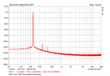
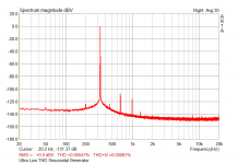
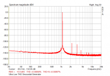
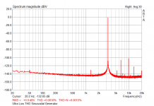
and this last one is acquired thru a SVF notch with auto-nulling (post notch gain: 40 dB):
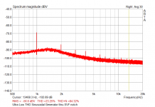
THD @ 1kHz, 3Vrms out seems to be somewhat lower than 0.0001% (or -120 dBc - notch input level is scaled down to 1 Vrms), while ARTA says it's more than an order of magnitude higher - I'm likely looking at the EMU's intrinsic THD, which falls in the 0.0005-0.0003% range below 1 kHz - EMU says: THD+N (1kHz at - 1dBFS, min gain): -103dB (.0007%).
The SVF generator is based on a T&H-S&H peak detector and uses an OTA (LM13700) as level controlling element; output level is stable within +/- 0.1dB from 50Hz to 110kHz, settling time at startup is about 5 secs @50Hz (too high, imho), and almost instantaneous above a few hundreds Hz (say 300 Hz). Though this prototype is almost 1 year old it's still in an early stage of development, and needs to be optimized in almost every respect: I'm not fully satisfied both with the OTA (planning to use a FET-based multiplier) and the level controlling loop; ripple from the peak detector is somewhat too high, which means that THD (and THD+N...) can be lowered a bit. Well, it's a long and winding road, you know, and I'm a little bit short of spare time to work on it - nevertheless, it rocks 🙂 : the T&H-S&H peak detector is probably the best choice if you are looking for low THD, continuous coverage and fast settling. Surely you can manage to obtain even lower THD levels with a standard peak detector (maybe a 4-phase) at the expense of slower settling and trickier range switching...
Cheers,
L.
Using a Dick Moore's twin-t notch filter I can null the fundamental enough to to allow the some of the harmonics to show on my HP 3562. The attached is the spectrum at 1vrms, 10khz of the KH4402. Ignore the the THD number which is calculated by the HP8903A. This specturm calcs at .00018% last time I checked. With the Juli@ card set for 192khz I get results out to about 90khz, although the resolution starts to rise upward for the last 20khz or so.
Attachments
Rather, what i found was the importance of the distortion introduced by the agc element, namely the JFET variable resistor in my case.
A simple approach to reduce multiplier contribution is to parallel several multipliers. As this reduces their noise contribution, they may be operated at lower nominal level and thus contribute less distortion. Also the use of an opamp with low voltage noise instead of the NE5534 will reduce multiplier noise considerably, and thus allow lower operating levels.
I found that it is valuable to trim the feedback ratio to the gate, as the generally-accepted value of 0.5 is not always optimal.
What deviation from the theoretical value did you find?
Another important point for oscillators in a THD analyzer application is phase noise and amplitude noise.
What is the operating level of the SV filter in your design? Near the oscillation frequency the electronics has very high noise gain; this may look like amplitude noise induced from the AGC. Unlike such, it can be reduced by increasing the operating level of the SV filter.
-140 dB, preferrably -160 dB
Even -140 dB is exceedingly difficult to measure.
Let's start with a Krohn-Hite 4402 and improve the (noise + distortion) by 20 dB or so.
It think most of these specifications would be possible to meet, at considerable complexity and cost. A good starting point would be the AP System One design. From there we need several optimisations:
* Replace the NE5534 in the main signal path with low distortion opamps such as LT1468, or possibly even a composite opamp topoloy or discrete implementation.
* Replace the JFET switches in the main signal path with relays or possibly CMOS switches with low on-resistance (this will need some means to render distortion from off-capacitance negligible).
* Optimise the track & hold stage for low hold-mode feedtrough and the sampel & hold stage for low pedestal errors.
* Optimise the multiplier with the means outlined above, or use a discrete design based on a translinear gain cell.
This of course are just very general hints; obviously there are numerous details, and only a very systematic design approach which attempts to isolate, quantifiy and reduce every single contribution will give satisfactory results.
If I'd attempt to design another "as good as it gets" oscillator covering a 10 Hz-100 kHz frequency range I'd split the frequency bands; i.e. design four dedicated oscillators for decadic ranges (10-100 Hz, 100 Hz-1 kHz etc.). This allows much easier optimisation (in particular of the level detector, but also of the opamps and multiplier).
Samuel
- Status
- Not open for further replies.
- Home
- Amplifiers
- Solid State
- My implementation of the Cordell Distortion Analyser
