

flux01 said:
So would 4 of these $9.95 MECI heatsinks (I'm assuming 2/channel) be enough for the Zen IV? Does anyone have any experience with how good these heat sinks are?
Cheers,
Dave
I used those last winter in a mini-a and measured
a 21C temperature increase with 30W. The ambient
temp was around 20C.
Dennis
I am quite new to trying to understand heatsinks.. hope I going the right direction.
Say one channel dissipates 100 watts and 4 output devices. This means each output mosfet produces 25 watts of heat. If I want to use a single heatsink for all 4 devices, with the devices heating up a maximum of 30 degrees C, then the heatsink must have a rating of 0.3 degrees C / W? Which means for each watt dissipated, the heatsink will increase 0.3 degrees celcius?
Say one channel dissipates 100 watts and 4 output devices. This means each output mosfet produces 25 watts of heat. If I want to use a single heatsink for all 4 devices, with the devices heating up a maximum of 30 degrees C, then the heatsink must have a rating of 0.3 degrees C / W? Which means for each watt dissipated, the heatsink will increase 0.3 degrees celcius?
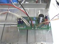
François said:Transistor assembly is like this
Mach_Y said:I am quite new to trying to understand heatsinks.. hope I going the right direction.
Say one channel dissipates 100 watts and 4 output devices. This means each output mosfet produces 25 watts of heat. If I want to use a single heatsink for all 4 devices, with the devices heating up a maximum of 30 degrees C, then the heatsink must have a rating of 0.3 degrees C / W? Which means for each watt dissipated, the heatsink will increase 0.3 degrees celcius?
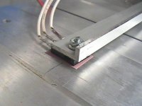
Francois, the heat of your amp would be dissipated/distributed more evenly if you clamp a flat bar 2-3 inches across your heatsinks with a generous amount of heat transfer goo between it and the heatsinks. Mount the power transistors on this bar with ht goo under the mica insulators. I believe your heatsinks in one continous length can dissipate the heat of a 2.8A biased zen.
Mach_Y, that is right.
A good source of hsinks is ThermaFlo (thermaflo.com) Contact person is Gary Kuzmin (gkuzmin@thermaflo.com). He did a good job getting my heatsinks.
First one is closeli_gangyi said:Just a bit off-topic...Francois...does your name happen to be pronounced "fan--zwah" or something?? Not just "frank-oh-is"...??
")
Blues said:
Francois, the heat of your amp would be dissipated/distributed more evenly if you clamp a flat bar 2-3 inches across your heatsinks with a generous amount of heat transfer goo between it and the heatsinks. Mount the power transistors on this bar with ht goo under the mica insulators. I believe your heatsinks in one continous length can dissipate the heat of a 2.8A biased zen.
Mach_Y, that is right.
A good source of hsinks is ThermaFlo (thermaflo.com) Contact person is Gary Kuzmin (gkuzmin@thermaflo.com). He did a good job getting my heatsinks.
Believe me, the heat transfer between the device and the heatsink is not the problem. All the chassis is hot after a few hours. The problem is the surface exposed to the ambiant air. I need bigger heat sink with more fins.
Mosfet extension off PCB
François, et all
I see you have mounted the mosfets direction to the heatsink and use long hook-up wires to the PCB.
I'm in the middle of chassis design for a balanced ver. Zen 4 but not sure on how to effectively handle heatsinking. Most seem to mount the mosfets with the PCB ON the heatsink. But with using multiple sinks and the way the PCB are layed out, you're normally forced to use a bar which mounts across all the heatsinks.
Can someone give some insight why it is bad to extend the transistors OFF from the PCB?
BQ
Heat Dissipation ?
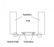
Please comment on the possible heatsinking problems shown in the photo. Somehow I don't like the idea of extending the transistors off from the PCB (makes like an antenna) so I have thought of mounting them on to a common bottom plate chassis where the heatsinks are attached to.
Where i've placed a circle in the diagram, would this be a concern of how much heat dissipation will transfer to the heatsinks from the bottom plate? Of course the heatsinks will have the silly white heat transfer compound.
BQ
Attachments
Re: Heat Dissipation ?
I have already a definitive zenv4 (non bal) wich have the transistors 12cm away from the PCB. I just cared to mount the 220ohm gate resistor directly on the gate pin of the IRFP044.
Super_BQ said:Somehow I don't like the idea of extending the transistors off from the PCB (makes like an antenna)
BQ
I have already a definitive zenv4 (non bal) wich have the transistors 12cm away from the PCB. I just cared to mount the 220ohm gate resistor directly on the gate pin of the IRFP044.
Attachments
Re: Heat Dissipation ?
IMHO , the chip temperature will be way too high , expecially if your bias intention is 2 amps.
Super_BQ said:Please comment on the possible heatsinking problems shown in the photo.
BQ
IMHO , the chip temperature will be way too high , expecially if your bias intention is 2 amps.
- Status
- This old topic is closed. If you want to reopen this topic, contact a moderator using the "Report Post" button.
- Home
- Amplifiers
- Pass Labs
- my heatsink calcs for Zen v4