Damage control
Will the CD be exposed to anyone who want's to touch it?
Isn't it a bit dangerous?
If a bug nests in the CD and you turn it on you migth get a bug paté on your nose or worse in your girlfried's nose!!! ( that way U don't get married!)
What about the laser? is it harmfull for the eyes?
Will the CD be exposed to anyone who want's to touch it?
Isn't it a bit dangerous?
If a bug nests in the CD and you turn it on you migth get a bug paté on your nose or worse in your girlfried's nose!!! ( that way U don't get married!)
What about the laser? is it harmfull for the eyes?
Re: Damage control
> Will the CD be exposed to anyone who want's to touch it?
sure, that's part of the fun.
> Isn't it a bit dangerous?
nah. i don't have kids or pets.
>If a bug nests in the CD and you turn it on you migth get a bug paté on your nose or worse in your girlfried's nose!!! ( that way U don't get married!)
that's ok i intend to stay single for a while.
> What about the laser? is it harmfull for the eyes?
not unless you look directly into it. you'd have to stare at it all day. or, at least an extended period of time.
doesn't matter now anyway, i put my player back together, i got a new one so i'm giving this to my brother. it was kind of fun all taken apart but i admit it was pretty inconvenient.
SMT (De)soldering
Hi ,
I once posted on AA how we did the SMT work.")
http://www.audioasylum.com/audio/tweaks/messages/50594.html
Hi ,
I once posted on AA how we did the SMT work.
http://www.audioasylum.com/audio/tweaks/messages/50594.html
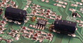
Right now I'm busy writing up a section on SMD rework for the diyaudio wiki. I'm not done yet, but I'll include some photos from my NS-500V modifications to show how it's done. That air pencil I built turned out to be the show-stopper when I was doing the rework, and I highly recommend one to anyone considering modifying anything with SMD parts on it.
With a real professional hot-air gun I've seen 208-pin TQFP packages lifted off a circuit board like they hadn't even been soldered in the first place! Once all the solder is melted, the part just falls off! (ok, actually you lift it off with a dental pick or vacuum pick-up tool).
Anyway, I'll post more and add some pics to the wiki soon, including a description of how I made the hot-air pencil.
Oh, BTW - the opamp I replaced the 4558 with was the AD8620, and I'm very impressed with the result! The '8620 is a very nice chip, and this is the first time I've used it. I might try OPA2134's for the 6-channel outputs, just as a comparison, even though the 6-ch DAC doesn't sound as nice as the 2-ch DAC.
Pics from my 500V mod to be posted to the wiki soon!
Pics from my 500V mod to be posted to the wiki soon!
Turn-on/off transients gone!
... so I ordered the service manual for the NS500V from Sony, and it arrived on the weekend. Superb! Full schematics, block diagrams, PCB layout guides, and assembly/disassembly procedures... index of part numbers and replacement stock numbers etc... everything you need to know
I've now rigged up the audio section so that the mute transistors can be removed entirely and there will be no clicks and pops during power-up/down...
The trick was to supply the audio section from the EVER-11V signal, which means that the audio opamps and DACs will always be powered, even during soft power-down. Thus, you can turn the unit on and off with the remote control, and when it goes into standby, there will be no voltage spikes on the outputs. Of course, this doesn't totally eliminate the problem, as there will still be transients during hard power switching with the mains plug or main power switch.
Also, I completed the other modifications, including mute transistor removal and opamp decoupling. Here's the details:
1st mod: new opamp - I replaced the crappy one with an Analog Devices AD8620... very worthwhile! I also added 1uF Panasonic HF supply decoupling caps (no HFQs on hand...).
Attachments
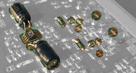
other mods to the analog output stage were:
- short out C247 and C248 (47uF electrolytics) output coupling caps with a small piece of trimmed component lead
- bypass R288 and R289 (470ohm each) series output resistors by stacking a 10ohm resistor on top.
- remove muting transistors Q213 and Q214
- remove C280 and C281 (220pF) caps to ground
- bypass R323 and R325 (470ohm) series output resistors with 0ohm resistor stacked on top
The stereo outputs now have nothing but just under 10ohms between the opamp output and the panel jack. In combination with the AD8620 and the power supply decoupling, the difference is astounding! There is a tremendous amount more detail and transparency, and the weak bass has been totally revived to a strong, punchy, clean and tight sound. I'm very very happy with the sound of these mods. The Rotel is now officially relegated to backup duty!
I also considered removing R324 and R326 to disconnect the 2nd set of stereo output jacks, but though it unnecessary in the end. If I encounter stability problems with the low output impedance of 10ohms, I can switch to the second set of jacks and have 480ohms series resistance in there... However, with the analog stages configured this way, I don't think it's wise to hook up more than one output at a time, so it may be better to disable the second set to prevent this hookup by someone else.
Here's a pic with all the changed elements highlighted:
Attachments
OK, now here's how I got around the lack of output mute:
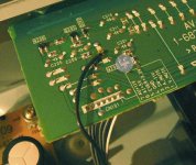
To accomplish this, I wanted the opamps powered at all times so that there aren't any power up/down transients. Q201 controls the switching of the power to the audio stages (DAC power included), and it is enabled when SW-11V power supply line coming in from the IF-84 board is turned on. This activates Q206, which turns on the +11V supply to the audio section. As long as the negative supply is present, the positive side will turn on too. So, I removed Q201, and fed -11V in directly from the power supply, before it gets switched at the control board. It's the same line, just tapped before the control board switch.
The attached photo shows the AV board with Q201 removed, and the wire added to bring in EVER-11V from the IF-84 board.
Attachments
Finally, I poured over any related schematics to make sure I wouldn't mess up any other part of the circuit, or interfere with the operation of the player in any way, and I'm confident that it wont, especially after testing it out with all sorts of discs containing different audio formats... dts, SACD, CDDA, DVD video with Dolby Digital sound, etc... it all works just fine. The only parts of the player affected by the power supply mod are the opamps and the DAC chips, which are all now continuously powered as long as the main power switch is on.
I was worried initially that the DACs wouldn't get properly initialized without a power cycle, but there is a separate reset line for the DACs, and the DACs need to be reset after power-up anyway, so the player must reset the DACs anyway every time it thinks they're being powered up again.
Mission accomplished! No pops or clicks when the unit is switched to or from standby mode.
very nice
wiring the outputs straight to the jacks is a very significant mod, did it myself and liked the results. 10 ohms decoupling is a little on the low side (i used 100), did you verify with a scope that there were no oscillations when connected to the load (e.g. preamp)?
i recently blew up my NS500V. i hadn't screwed down the PCB right so the steel top cover shorted everything out, and i haven't had the motivation to diagnose it yet... i may have to get a new one altogether if the digital board got destroyed in the process. oh well...
Brian, i'm not sure which i would mod first. probably the CE775. i have the 222ES (ES version, same player) and it is a lot cleaner inside. however, i think i actually prefer the sound of the AKM DACs in the NS500V to the BB ones in the 775/222. but the circuit topology of the 775/222 is definitely superior.
Yeah, 10 ohms is a bit low, I'd normally go with something like 30 or 47 for something like this, but I'm driving very short cables to the preamp so capacitance is minimal...
I did verify it on the scope, and the output was quite clean - no spurious oscillations and whatnot. I also tried a couple of small caps across the outputs to test stability, and it seemed just fine. In retrospect, I should really do a more thorough test with some square wave signals to check for ringing. I think I have a test disc around here somewhere...
I have to say that the biggest improvement with the decoupling caps and removal of series output resistance has been the bass. That soft and weak bass is totally gone, replaced with a clean, solid, fast bass that has no hint of bloating. It's much more rhythmic, and much fuller now. Before, I never felt the same involvement with the music that I got with my Rotel, but now that thin persona is mostly gone, and the music sounds much more alive again!
Sorry to hear about the disaster. It really sucks when these things happen With luck, things just got shorted to ground, in which case it should mostly be power supply parts that are blown,and not the expensive or difficult to replace ICs. I should take note and insulate the inside of my lid with something before it happens to me too. If you don't have the service manual, you should consider it... well worth the $30 or so. Email me if you'd like more info...
I did verify it on the scope, and the output was quite clean - no spurious oscillations and whatnot. I also tried a couple of small caps across the outputs to test stability, and it seemed just fine. In retrospect, I should really do a more thorough test with some square wave signals to check for ringing. I think I have a test disc around here somewhere...
I have to say that the biggest improvement with the decoupling caps and removal of series output resistance has been the bass. That soft and weak bass is totally gone, replaced with a clean, solid, fast bass that has no hint of bloating. It's much more rhythmic, and much fuller now. Before, I never felt the same involvement with the music that I got with my Rotel, but now that thin persona is mostly gone, and the music sounds much more alive again!
Sorry to hear about the disaster. It really sucks when these things happen
With luck, things just got shorted to ground, in which case it should mostly be power supply parts that are blown,and not the expensive or difficult to replace ICs. I should take note and insulate the inside of my lid with something before it happens to me too. If you don't have the service manual, you should consider it... well worth the $30 or so. Email me if you'd like more info...oh yeah
hifizen, i noticed you bypassed stuff on the output stage by shorting out the components on the PCB. i actually went one step further - i conncted a 100 ohm Holco directly from near the opamp output pad to the output terminal, using teflon tubing to insulate the resistor leads. this way you can avoid the flimsy PCB traces and extra solder terminals and use a better quality resistor. i'll try taking a picture sometime, once i get the thing working again...
hifizen, i noticed you bypassed stuff on the output stage by shorting out the components on the PCB. i actually went one step further - i conncted a 100 ohm Holco directly from near the opamp output pad to the output terminal, using teflon tubing to insulate the resistor leads. this way you can avoid the flimsy PCB traces and extra solder terminals and use a better quality resistor. i'll try taking a picture sometime, once i get the thing working again...
oooh, good idea. Yeah, I guess when I initially did the mods, I was looking for maximum "reversibility" so I can restore it easily if the mods don't work out... basically, removing as few components as possible. Hence the stacked SMD resistors (fewer parts where I have to deal with that glue!). I was also able to do all these mods without removing the AV board from the chassis (heh, how lazy is that?). For now, the unit is humming along nicely, I think I'm done with mods on it for a while. Next time I crack it open, I'll see what I can do about arranging some sort of direct wiring to the jacks, maybe cut some traces here or there. All in all, the PC traces aren't so bad... at least they have very nicely laid out guard traces  .
.
.well...
my poor NS500V is still dead (shorted power supply). but, i will be building a new supply soon! simple pass transistor for analog supplies, LT1085 for the digital supplies (i'm lazy). i've started modding my C222ES change as well but i'm really not fully satisfied with the sound of its BB PCM1702 DAC's... it miss that magical life that the AKM DACs in the NS500V had. might do a clock upgrade as well, if i have time...we shall see. more to come.
my poor NS500V is still dead (shorted power supply). but, i will be building a new supply soon! simple pass transistor for analog supplies, LT1085 for the digital supplies (i'm lazy). i've started modding my C222ES change as well but i'm really not fully satisfied with the sound of its BB PCM1702 DAC's... it miss that magical life that the AKM DACs in the NS500V had. might do a clock upgrade as well, if i have time...we shall see. more to come.
new thread
a few of us are hoping to start a mod project:
http://www.diyaudio.com/forums/showthread.php?threadid=8557
a few of us are hoping to start a mod project:
http://www.diyaudio.com/forums/showthread.php?threadid=8557
I'm confused...
I'm ready to rip open my NC650V tomorrow to do some mods finally - several months later.
I've been going over schematics tonight, preparing and looking to understand what I'd be doing tomorrow. From what I can see, the muting BJT switches (say Q220 and Q221 on page 69 of the manual) are NOT in the signal path. I don't understand how getting rid of these is going to help with the sound quality at all. The modification of running the power supply line to keep the output opamps on at all times (well, at least during standby mode) doesn't seem to make any sense to me. Getting rid of these seems to be creating a problem that otherwise doesn't exist (the nasty power on/off thump transients) rather than providing a solution to a problem that does exist.
The only complaint I can relate to would be the 470 ohm resistors in series with the signal path. These obviously form a current limiter for the muting switches. If getting rid of these 470 ohm resistors is paramount to increasing sound quality, then I guess I'm all for the modification. But, wouldn't it be possible to just place a smaller (say 100 or 47 ohm) resistor in between the collectors and ground?? This would also provide a current limitation and at the same time absorb most of the "thump" transient current because it would have a much lower resistance than the input impedance of the preamp/reciever that the player is connected to. So, here we're talking like a 100 ohm resistance to say a typical 47k input impedance to a preamp. This means about 0.2% of the current would be placed into the preamp, while the other 99.8% would be dumped right to ground through the 100ohm resistor/BJT switch combo.
The only question that now remains is, can the BJTs handle that kind of current? Assuming that the max voltage that could go through would be the power supply voltage to the opamps of about +/-11V.... which gives us: 11V through 100ohms -> 110mA. A typical BC550 or 3904 BJT is rated for about 100mA and 200mA (respectfully).
So, under these spike (very short time constraint) conditions, I would think that this could be a possible solution, without having to reroute power inside the player. And there's the added bonus of NOT having to worry about forgetting to turn off the preamp or amp prior to shutting of the Sony player in fear of obliterating your precious Scan Speak woofer cones.
I'm assuming that the BJTs that Sony used for the player are probably SMT, so they probably also have a much lower power handling capability. In this case, I propose removing the current BJT and soldering in, say a 3904 with a resistor placed in series with the collector and the connection back to the ground lead on the PCB. Also (obviously) remove the 470 stock resistor and short this out with a piece of wire. Then add (depending on requirements of your particular interconnects) say a 47-100 ohm resistor of better quality in series with the lead connected to the emitter of the 3904 and the positive lead of the RCA connector (thus, bypassing the switch/relays after the mute circuitry).
Comments? Suggestions?
Thanks,
- Status
- This old topic is closed. If you want to reopen this topic, contact a moderator using the "Report Post" button.
- Home
- Source & Line
- Digital Source
- my hacked-up Sony DVP-NS500V SACD player