MikeB,
Good work, just one remark that might help:
How about you give the predriver/levelshifter a little bias voltage, so that the voltage swing needed for it to switch levels is lower, hence it'll be more like a schmitt-trigger?
Best regards,
Sander Sassen
http://www.hardwareanalysis.com
Good work, just one remark that might help:
I had some sucess with adding a 3nf to the Re of predriver/levelshifter.
How about you give the predriver/levelshifter a little bias voltage, so that the voltage swing needed for it to switch levels is lower, hence it'll be more like a schmitt-trigger?
Best regards,
Sander Sassen
http://www.hardwareanalysis.com
Hi Ssassen !
The problem is, that i create the necessary deadtime by not having
biased the predriver, giving a delay turning on these transistors...
So i use these 3nf to create some nearly overshooting, resharpening
the edges of the signal... The effect of this was very visible on scope,
the signal went from nearly sinusoidal to nearly squarewave.
Looking to the pchannel-vgs explains why i need that much deadtime...
Some small sidenote...
I still can't believe how superior the sound of ClassD is compared to
analog amplifiers... It plays details and dynamics that effortless !
And turning up the volume just makes the music more intense, not louder !
Even this far from perfect simple ClassD plays at a qualitylevel... Holy shid !
Mike
Thanks MikeB,
Alright, how about the following modification? I devided the 3nF cap up in two 1.5nF caps and attached their center to the Vcc, this should help speed up the rise/fall times and it sure is easy to try. See below quoted schematic, I edited in the changes.

Best regards,
Sander Sassen
http://www.hardwareanalysis.com
Alright, how about the following modification? I devided the 3nF cap up in two 1.5nF caps and attached their center to the Vcc, this should help speed up the rise/fall times and it sure is easy to try. See below quoted schematic, I edited in the changes.
Best regards,
Sander Sassen
http://www.hardwareanalysis.com
Hell yah Mike well said.
It is impressive how even crappy class d can sound is it not? Makes it worth experimenting on your own even if only in P2P. Since I'm contemplating making another more complex version (than I've done before) using veroboard I'd very much to see the bottom side of your yours, would you be so kind as to provide a pic of it please?
I have to point out one thing that really sucks though about experimenting like this, eventually it gets to be really very good, but there's still certain "things" that will rub you the wrong way... and how to get rid of those right? Dual layer PCB.... SMT.. sniff.
It's hard to hit that point where you just have to admit to the limitations of the way it was built, and walk away from it leaving it "unperfected". Still lots of fun though.
You mentioned using the heatsinks as some sort of shielding.... they might be making better transmitters, which your coil might pick up nicely. It seems well worth bolting a small HF bypass cap to each heat sink, espcially given where you take your feedback from.
Seriously I'd like to see the bottom side of that board. Excellent work as well.
Best Regards,
Chris
Re: Update
Yes, my bad, I just looked at my post and noticed I put gain of predriver 200 instead of 20. Sorry for that.
Interesting that you actually limited the drive voltages by limiting the gain on the Vas via the 150 ohm resistor. If you have the time I would appreciate if you could write why you decided for that approach?
That would be about their usual price. I'm just asking because there are differences between manufacturers, speciffically in the threshold voltage. I only have IRFP140 and IRFP140N datasheets at hand at the moment and there is a good 1V of difference, lower on the N part. But looking at your diagrams and oscillograms I don't think this is the case for you.
Yes, looks like that may actually be the problem. 4V puts it right in the middle of the 'linear' area. Also, it seems like you could be having some source inductance (or stray inductance) issues re ringing? The sticking part seems to last about as long as the ringin part, and the sticking part shows a ringing crest.
It's difficult to accurately overlay the P and N gate drive waveforms, maybe that would reveal cross-conduction during the sticking part on the P side?
MikeB said:Okay, here is the "exact" calc for the Vgs:
The gain of the predriver/levelshifter is ~14, given a virtual additional Re of 20ohms you get 1000/(50+20) = 14. The currents delivered by "vas" are ~8ma, this gives voltageswing of 1.2volts because of the 150ohms to ground.
Yes, my bad, I just looked at my post and noticed I put gain of predriver 200 instead of 20. Sorry for that.
Interesting that you actually limited the drive voltages by limiting the gain on the Vas via the 150 ohm resistor. If you have the time I would appreciate if you could write why you decided for that approach?
MikeB said:But, it all seems to be the problem with too slow switching off...
Theoretically both mosfets are IRF, but you never know what you really get... Both mosfets have the same labeling, using the IRF-brand, the IR with the diode between. But they costed only 60cents...
That would be about their usual price. I'm just asking because there are differences between manufacturers, speciffically in the threshold voltage. I only have IRFP140 and IRFP140N datasheets at hand at the moment and there is a good 1V of difference, lower on the N part. But looking at your diagrams and oscillograms I don't think this is the case for you.
MikeB said:I will try to improve the driverstage, as the pchannel-vgs shows some "sticking" when vgs drops below 4volts... Also there is some ringing in the vgs.
Yes, looks like that may actually be the problem. 4V puts it right in the middle of the 'linear' area. Also, it seems like you could be having some source inductance (or stray inductance) issues re ringing? The sticking part seems to last about as long as the ringin part, and the sticking part shows a ringing crest.
It's difficult to accurately overlay the P and N gate drive waveforms, maybe that would reveal cross-conduction during the sticking part on the P side?
Hi !
SSassen, there would be one small problem with your modification...
If you look at the scopeshot of the output, you see that Vcc is not
stable, it wings with some volts. Or is this the idea to create some
feedback ? But, i must admit, i don't understand your change...
Bgt, changing the feedback isn't that easy, i already checked, it would
need heavy changes, because of the thresholds of the schmitt-trigger
beeing to big, i would not get above 100khz oscillation...
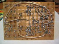
Chris, i attached a shot of the first prototype bottomside...
(This one used folded cascode for levelshifter)
It misses the 3 paralelled 1nf-caps...
I added one 1nf after the other until i reached near overshooting !
Yes, a PCB would help improve the signals, and should greatly
reduce ringing. But my intention with this amp was to make a simple
amp, easy to build (this excludes SMD) using standard components,
so that everyone can build this. Just to get back to the DIY-spirit like
it is with solidstate-amps. Just build and listen... No exotic parts...
It took me ~4 hours to construct the whole thing... (and 2 weeks to design...)
I think, if i can reduce deadtimes, it should evolve from "crappy" ClassD
to serious amplifier.
At least it does not sound crappy... Really !
But i consider to switch to n-channel only, seeing how cold the
nchannel keeps, and looking to the IRF-page seeing the newest
mosfets specifically developed for ClassD...
Looking at the datasheet just makes my mouth wet !
Have you looked at the irfb4212 ? Ouch ! 40ns recoverytime!
Another thing... I always observed temperatures of transistors, but
when listening for longer period, i wondered what was stinking...
The outputcoil heated up ! How is this possible ? I would expect
several amperes to heat up a 1mm-copperwire !
Is this normal or is there another problem ? The coil was too hot to
touch for longer than a second, burning my "fingometer"...
I would estimate above 80°C ... An aircoil !!!
At least the caps were cold, seems that wima-mks2 are real serious quality...
Mike
SSassen, there would be one small problem with your modification...
If you look at the scopeshot of the output, you see that Vcc is not
stable, it wings with some volts. Or is this the idea to create some
feedback ? But, i must admit, i don't understand your change...
Bgt, changing the feedback isn't that easy, i already checked, it would
need heavy changes, because of the thresholds of the schmitt-trigger
beeing to big, i would not get above 100khz oscillation...
Chris, i attached a shot of the first prototype bottomside...
(This one used folded cascode for levelshifter)
It misses the 3 paralelled 1nf-caps...
I added one 1nf after the other until i reached near overshooting !
Yes, a PCB would help improve the signals, and should greatly
reduce ringing. But my intention with this amp was to make a simple
amp, easy to build (this excludes SMD) using standard components,
so that everyone can build this. Just to get back to the DIY-spirit like
it is with solidstate-amps. Just build and listen... No exotic parts...
It took me ~4 hours to construct the whole thing... (and 2 weeks to design...)
I think, if i can reduce deadtimes, it should evolve from "crappy" ClassD
to serious amplifier.
At least it does not sound crappy... Really !
But i consider to switch to n-channel only, seeing how cold the
nchannel keeps, and looking to the IRF-page seeing the newest
mosfets specifically developed for ClassD...
Looking at the datasheet just makes my mouth wet !
Have you looked at the irfb4212 ? Ouch ! 40ns recoverytime!
Another thing... I always observed temperatures of transistors, but
when listening for longer period, i wondered what was stinking...
The outputcoil heated up ! How is this possible ? I would expect
several amperes to heat up a 1mm-copperwire !
Is this normal or is there another problem ? The coil was too hot to
touch for longer than a second, burning my "fingometer"...
I would estimate above 80°C ... An aircoil !!!
At least the caps were cold, seems that wima-mks2 are real serious quality...
Mike
Attachments
Hi ilimzn !
The mosfets where matched to Vgs-threshold of 3.6v...
But even with the same manufacturer i had one irf9540n having
a vgs-treshold above 5volts...
I choosed the 150ohm in the vas to get very low zout, because of
the highly reactive load from the bases in the levelshifter.
Even with this 150ohm these are visible on the scope, but only some minor spikes.
Also i wanted to have 1.2v swing, to be able to cut the signal at
it's half, to create all the deadtime i want.
Also, a that small resistor speeds up the vas like hell, but with the 1nf...
I believe this sticking part in the Vgs-waveform of the p-channel is the
reason why i need that much deadtime !
Very interesting is, that this stucking seems to occur exactly at the
vgs-threshold, when the mosfet finally closes...
In sims this effect is not visible. Impossible to design ClassD without scope !
I made some checks in sims, without any crossconduction the losses
in the pchannel are ~650mw, enough to heat up that small heatsink !
I think, right now i have no crossconduction, just way too high rds-on...
Mike
Hi,
Well Mike thanks alot now I'm ashamed of my work after seeing that. I'm not shy to say this either, the bottom of your board is cleaner than the top of mine. I was keeping my "good perboard" for the second project though, this one has traces, and by using them I see now I've compromised my layout, which I'm paying for now because it's noiser than it was on a protoboard. Before I give up on it though I'm going to try re-routing a few things (is it there yet?).
Hey you know when I said "crappy class d" I didn't at all mean "your crappy class d" but rather the non store bought, tuned to perfection with many hours of listening tests along side of an AP2, using the very best construction techniques going ..
Basically class d the DIY way (they said it couldnt' be done!).
I fully agree with you anyway, the dynamics from them put your average amp to shame, and I find you can tell that right away, well before any optimizing has been done.
I placed my PNP turn off transistor right on the mosfet pins on the underside of the board. The turn on transistor is about an inch away on the top side, would have been closer but I had to place it around the heatsink.
The IR device you mentioned really does look good, I hadn't seen it before. I'm using FDP3682 N-channels from Fairchild. They stay perfectly cold now.
I'm also using an aircoil, though mine is much smaller. At no point in time along with all the changes and mods I've made to the circuit has that coil ever even gotten warm. I tried a toroid once with a mystery iron powder core and that got a little warm. It also didn't sound as good, but it lowered the noise floor notably. You have about twice the rail voltage I do though.
Maybe you need a bigger gauge of wire/fewer turns, lower the DC resistance? As others have said though, a good toroid would be best anyway, but you did some kind of job making that up and keeping it one piece. I "painted" mine with 5 minute epoxy, it only has about 18 turns, holds it together well though.
Anyway I really admire your true DIY approach and your goal with this project. If it helps you to know you've inspired me already to continue with my next project using the same sort of board you are, as I now see it's much cleaner than my previous approach, and just this morning I was thinking I wouldn't bother with it because it would likely be worse. So thanks for that picture. I'm looking forward to following your progress with this.
Best Regards
Chris
MikeB said:...outputcoil heated up ! How is this possible ? I would expect
several amperes to heat up a 1mm-copperwire !
Is this normal or is there another problem ? The coil was too hot to
touch for longer than a second, burning my "fingometer"...
I would estimate above 80°C ... An aircoil !!!
At least the caps were cold, seems that wima-mks2 are real serious
Hi Mike, I attribute this wire heating to the skin effect. It causes the current to flow on the surface of a wire at high frequencies. On one of my early switching power supplies, the enamel insulation on an air core choke actually developed cracks from the heat. Consider too, that the coil conducts more current than is output to the load.
Also, you may be able to lower radiated interference from your coil on the circuit by winding it in two sections, half in one direction, the other half physically oriented at a 180deg angle to the first.
Hi !
Chris, point taken... I did not understand the "crappy" like mine beeing bad...
Of course it is not optimized yet, it's even not cold yet !
But, it works !
And yes, i wanted to proove that you can build ClassD the old fashioned way !
My coil has 60 turns, giving in theory 55uH, made of 2.5meters wire !
What kind of noise are you talking about ? I did not hear anything...
I like these boards, they are very good for just building a prototype !
But when you start changing, they become a pain...
What oscillationfreq do you use ? How cold is your amplifier ?
Is yours fully discrete, or do you use the ir2011 ?
I forgot to mention.. I even "forgot" to isolate the mosfets from
the heatsinks ! So, the 300khz squarewave is fed into the heatsinks...
About the coil... When i was ready winding it, i found it very flexible,
just like a spring, very unhandy. So i just attached these stripes, making
the thing rock-hard !
Is it possible that mechanical resonance is heating up the coil ?
subwo1, if the skineffect causes this, the "dc"-resistance gets very high ?
Isn't there a specific winding-technology, like using twisted wires ?
Sims say that i have ~400ma current through the coil. (idle)
If i put 2 coils in reverse direction, don't they cancel out each other ?
I think Mr.Evil's suggestion, to bend the coil to a toroid could make
a perfect job to contain the field within the choke...
Mike
Hi MikeB, the fields would cancel if the windings were not separate and oppositely oriented (side by side) but concentrically wound in opposite directions (one winding around the other). So twisted wires wound into a coil would give very little inductance too. I think the minimum external field would result if two of the toroidal shaped air cores wound in opposite directions were placed one on top of the other.
I think it does if for no other reason than the temperature of the whole wire becomes elevated. Even though the low frequency audio component may be able to pass through the inside of the wire, the wire would still heat from the outside to the inside.
...if the skineffect causes this, the "dc"-resistance gets very high...
I think it does if for no other reason than the temperature of the whole wire becomes elevated. Even though the low frequency audio component may be able to pass through the inside of the wire, the wire would still heat from the outside to the inside.
Hi Mike,
Well while I had the comparator/input portion on a cheap breadboard all I had for noise was a slight buzz and a faint hiss, which largely vanished as soon as I put some audio through it.
Now I have that same noise but louder, and if I try to turn it up even a fifth of what I could before it crackles. It seems to have gotten a bit better just from relocating my ground wire but there's more to be done before I call it a day.... at the same time, it plays audio and there's no smoke..... running _COLD_... so I'm ready to leave it as it is, call it a done deal and move onto the next one. This is mostly because of not having a scope to tweak it with.
That's the funny thing see I can't really tell what the frequency is... It should be ~300kHz and it does a great job with the high notes.
How cold is it? It's cold Mike. Even at idle or low volume. I'm now using my upper lip'ometer on the heatsinks and they stay at room temp, +-18V rails/4ohm speaker load, from idle to full volume, doesn't matter. I tried putting my finger on the mosfet itself and it's only a bit warmer than the heatsink, still cool.
I'm using 100 ohm turn on resistor with the FDP3682 mosfets.
Originally these mosfets couldnt' last ten seconds in it and I had to use IRF640's which ran hot as all hell but lasted for a good while.
I'd like to put it on a scope one day soon, working on getting a cheap one. If/when that happens I'll optimize it further.
It is a most basic version of the fully discrete UCD. Next one will be fully differential and use better parts, I'm also going to go a bit higher on the rail voltage, but not by much.
Mechanical resonance heating the coil? Sure I'd imagine it would to some extent but I highly doubt anywhere near the heat you're seeing, in fact I would guess you'd have a hard time measuring any heating caused by that.
I think skin effect forces the AC signal, so your ripple frequency, towards the outer portion of the wire, and a bigger diameter wire would only help by providing a larger circumferance.
Ways to improve it all seem to have one thing in common, give it a thicker skin, or more of it.
That means you could try anything from winding your own air core out of foil (probably the best way I think) or using multiple paralleled strands of wire, or just a thicker gauge.
I was tempted to try the foil method but haven't yet done so yet.
How is your DC offset anyway? Maybe that could have something to do with it.
Also had you considered doing your level shifting via capacitive coupling?
Best Regards,
Chris
Hi !
As long as the coil does not smoke, i can live with that for the moment...
But a foilcoil, that would be great ! But can't make a toroidal winding
with foil...
I checked datasheet on the FDP3682, not bad, but this new IRF seems
to be slightly better for ClassD ?
Considering that the irf540n still has 77mohm Rds-on, given double the
supplyvoltage it is already impressingly cold. But on +/36v i would not
risk using a lip'o meter, imagine getting 80volts onto the tongue...
Why are you using only 18volts ? Did you already explode too many mosfets ?
I measured 7mv DC-offset, this should really cause nothing !
I think i have to get rid of this "stucking" in the Vgs-waveform,
This "nearly closed" state for ~100ns can't be good, this might be
the reason why the p-channel heats up.
Also, i could reduce deadtime by 100ns if i get rid of this !
Michael
Hi,
I had a 48VA 24V CT transformer which was used in a +-12V supply regulated to 1amp for a microcontroller, so I used it to make an unregulated supply. It's just what I had.
Not a bad voltage for experimenting with and with the speaker I have it's actually enough to annoy the neighbors with.
For the next one I'm planning on a slightly bigger supply though, 18Vac, 110VA.
BTW you said you forgot to isolate the mosfets from the heatsink and so the square wave is being fed into the heatsinks right. Even if you had isolated them I think it would be getting fed into the heatsinks anyway via capacitive coupling. Tying them to ground with a small cap seems to make a big difference.
Best Regards,
Chris
Yeah, i know what you mean... A long time i worked with a 15v
transformer, giving 21v DC... This was enough to torture my speakers
AND my neighbours !
I have isolated my problem... This stucking at exactly the Vgs-threshold ...
Very simple ! When the mosfet closes, the voltage at the drain jumps
to -Vcc because of the coil. But this transient "inducts" a lot of voltage
into the gate of the p-channel because of its D-G-capacitance, and
the driver for closing is not capable to deliver more current.
Now i could improve the driverstage or just do not use mosfets with
such big capacity... This excludes the use of p-channels...
Sims do not show this behaviour correct as the mosfets models are
simply BAD. It seems that realworld-mosfets are a LOT of faster than
sims say. Or the D->S capacitance is much smaller than in model,
giving a much faster transient ?
As the p-channel is stuck at this Vgs, it still conducts with quite
big current, but the drainvoltage falls to -vcc. So it conducts with
S->D voltage of 70volts, nicely heating up...
Good to know that this new IRF has only 66pf outputcapacity,
compared to the 400pf of the irf9540n.
Mike
Hi Carlos,
No problem that the DAT-recorder is stolen, i never used it for these recordings....
Will make some samples... But, sonics is not all with an amp, some
reliability and coolness is also important !
Just found out that sims are making bad games with me according
mosfet-models. Having scoped a lot i understand now much more
about these devices. Dropping Vgs below threshold instantly turn
off/reduce the current through these devices, not exactly 51ns later like some
value says in datasheet. Do you believe this, sim is just delaying the
response abut 51ns ? Means i have to do it the old fashioned way,
change parts and measure with scope... Damn it !
Mike
Hi Mike,
The small signal characteristics below Vth are basically unmodeled and should be seen as totally unreliable, as well as their variation with temperature or possibly even voltage. Things like base spreading resistance aren't accounted for at all.
Turn off behavior of the models/body diode recovery, is also said to be rather poor and unrealistic.
I think spice can be used to get a very basic running start at some ballpark values to start off with but it will def. need further optimizing in circuit.
Best Regards,
Chris
- Status
- This old topic is closed. If you want to reopen this topic, contact a moderator using the "Report Post" button.
- Home
- Amplifiers
- Class D
- My fully discrete ClassD