Re: HEADPHONE AMP
Not a good idea to have the AC connected directly without an isolation transformer. Not very safe. Also against the "official" rules in many places.
Besides a good power transformer shield the supply from the outside world ... so has a beneficial effect on sound.
dave
fdegrove said:It is technically possible though.You would need some automatic AC line phase detection circuitry.
Not a good idea to have the AC connected directly without an isolation transformer. Not very safe. Also against the "official" rules in many places.
Besides a good power transformer shield the supply from the outside world ... so has a beneficial effect on sound.
dave
Right,
I am trying to find all the components I need to build Aren van Waarde 's Single-Ended OTL Amplifier for Dynamic headphones. Once again, I have a few questions
1-For the potentiometer: What difference does it make to have a logarithmic or a linear potentiometer?
2-For the Resistor here is what is suggested to get for the Waarde amp
R1 - 1M ohms, 1 Watt carbon resistor
R2 - 33 ohms, 0.5 Watt metal film resistor
R3 - 47K ohms, 1 Watt carbon resistor
R4 - 820 ohms, 1 Watt carbon resistor
R5 - 4k7 ohms, 5 Watt wire-wound resistor
R6 - 3k3 ohms, 10 Watt wire-wound resistor
R7 - 10k ohms, 0.5 Watt carbon resistor
What difference does it make to have a carbon, metal film or wire wound? If for example for R2, I can only easily find a 33ohms, 2W metal film is it going to make a difference. In fact I have the opportunity to get them all for free as metal film 2W (except the 5W and 10W ones) would that influence the sound if they were all metal film instead of carbon?
3-For the capacitor here is what is suggested:
C1,C2 - 220 uF, 400 V electrolytic capacitor (Nichicon)
C3 - 220 uF, 100 V electrolytic capacitor (Nichicon)
C4 - 0.22 uF, 250 V MKT (DDR stock)
I have found C1 C2 and C3 however for C4 what does MKT means?
Waarde also says that C1 R5 and C2 are shared by both channels. Is that to save money and avoid having to buy them twice or is that for better sound quality?
4-Last but not least THE POWER SUPPLY is the point were I am having troubles, as fdegrove suggested I will try to go for the tube rectified one (http://headwize.powerpill.org/projects/showproj.php?file=waarde1_add_prj.htm)
However the only cheap transformer I could find is the following from Maplin
(http://www.maplin.co.uk/products/details.php?CartID=0209170926201443335&moduleno=6472&modulecode=)
I can’t figure out from the data given from maplin if it is suitable: why have a twin 0-115V input voltage? And what do they mean by secondary 350V max??(how can you change the output volatge anyway?)
Also if I have a separate amp and PSU what cable/connectors should I use between the two?
Thanks for your help
Jerome
HEADPHONE AMP
Jerome,
1/The pot must be logaritmic here since our hearing works in the same logaritmic way.
The linear pots are used for trimming voltages, etc.
2/The carbon restistors the designer suggests are a matter of taste.
You could use metalfilms as well as long as you respect the values and wattage ratings.
The 5 and 10 Watt resistors are wirewound types since the other types are not available in such high wattage.
These often are available as either regular (i.e. inductive) or non inductive.
For audio the non-inductive ones are desirable but you will notice a substantial difference in pricing of the latter.
Re: R2 is a grid stopper resistor.I would'nt put it there in the first place unless you get bugged by RF interference.
A value between 33R and 100R would do but stick with a 1/2W resistor.
Also I would accept the offer on the 2W resistors and use those iso the 1W.
3/C4 is not that critical (you can even ommit it).
Its sole purpose is to reduce the ESR (series resistance) of C3 at high frequencies.
MKT is metalized polyester film.You can use MKP (polypropylene) or MKC (polycarbonate).I think MKT is what he had in his spares box.
Keep it as close to C3 as you can when soldering it in.
You're right,he shares these components to save money and maybe he ran out of space too.It's certainly not for sonic reasons.
In fact the entire PSU is shared from what I saw.
I leave it up to you to double the outlay for a dual mono PSU or not.
If you have the space for it, putting in C1,R5 and C2 for each channel separately would improve on the design.
4/The Maplin transfo has spit primaries 115-0-115 to allow use of it in countries with 110/115 V mains.
In your case you HAVE to connect to the points marked 115V,you can use the center tap to connect the mains earth wire (green?).
HT secondary output voltage: 350V AC max.*
* Due to the internal winding impedance, max. voltage and current are not available simultaneously.
I can see why you are confused but depending on the circuit it is used in you can either design for max.current or max.voltage,not both at the same time.
Don't loose sleep over it,Maplin's just playing it safe.
You can change the output voltage in various ways depending on the type of rectification you use.
Re:Connectors?
The good ones usually don't come cheap depending on insulation quality.Don't forget you're carrying high voltages here.
Here is what I would do :
Bring out all wiring together from the PSU to the AMP with an appropriate cable and fix both ends with a tie wrap on the inside of the chassis to prevent damage from traction on the cable.(Or use appropriate cable clamps ofcourse.)
I haven't looked at how many conductors you would require.
Using a shielded cable would be a good idea,you can then connect the shield to the PSU chassis ground.
If you have the necessary tooling for heatshrinking you could roll your own?
Burndy,amongst others, has quite a range of good quality connectors if you decide to go down that road.
Happy building,
---------------------------------------------------------------------------------
HT secondary output voltage: 350V AC max.*
* Due to the internal winding impedance, max. voltage and current are not available simultaneously.
I can see why you are confused but depending on the circuit it is used in you can either design for max.current or max.voltage,not both at the same time.
Don't loose sleep over it,Maplin's just playing it safe.
You can change the output voltage in various ways depending on the type of rectification you use.
----------------------------------------------------------------------------------
Yes I am confused about that: What I understand is 350V is the output of the secondary (and it will always be 350V because it is set by the number of ‘loop’ in the winding). However depending on what is after the transformer (diode bridge, tube, capacitor, choke, rectification...) one can obtain a different voltage at the output of the PSU unit.
The current in the transformer will depend on the component in the PSU ‘after’ the transformer. (The above diode bridge, tube, capacitor, choke, rectification...) and of course everything after the PSU (the amp itself)
Do I start to get it? Or am I still completely wrong?
Yes, you are getting it. And you keep asking the right questions IMHO.
The tranny will basically "always" supply 350v like you said, what maplin is saying is that you should not draw maximum current...
And you're right when you say the dc voltage and current will differ as soon as you change rectification type (SS or tube) choke input or cap input etc., etc. (And the amp itself ofcourse)
HEADPHONE AMP
Jerome,
You,and Bas are right.Don't worry over it though.
The way they present the specs for their product is confusing to you because it differs from what you usually find in other catalogues.
What they mean is that when you draw 70W max current 250mA from it the measured AC voltage will be 313 VAC at that secondary.
Rgds,
OK, it becomes clearer now
The secondary winding as a resistor value of 300.5 Ohms so the more one draw current out of it the more the Voltage reduce:
350V at 0mA
Then at 125mA
(according to Ohm’s law: 350 – (Resitor * Current)
ie 350-(300.5*0.125)=313V
up to the max 250mA where the Voltage will have dropped to
350-(300.5*0.250)=75V
That’s a drop of 75V, does that happen in every Transformer or just in this one (hence the cheaper price)? And is it actually a problem?
The Next problem for me is to get the required 150VDC using the 350V Maplin transformer. (As you all probably guessed, I don’t know much in electronic, exept Ohm’s law).
I suppose I cannot just use the design given by Mingyao (http://headwize.powerpill.org/projects/showproj.php?file=waarde1_add_prj.htm) because The primary output of the Maplin transformer is not centre-tapped.
Can someone suggest a design/schematic I could implement using a 0-350V primary output transformer to obtain 0-150VDC (valve regulated if possible).
Also, Just a vocabulary question what do those mean: IMHO, tranny?
Thanks
Jerome
For IMHO and other acronyms use :
http://www.acronymfinder.com
Tranny is a different name for a transformer
All transformers...as far as I know will have that problem.
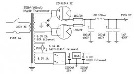
Yes you can use that design... there is a little trick that works like a charm...see this link from Andrea Ciuffoli
http://www.audiodesignguide.com/my/sep_pwr_mk2.gif
complete page is..
http://www.audiodesignguide.com/my/pse2.html
He uses 2 rectifier tubes but that is only because he draws a lot of current. The principal is the same..ie...you use 2 SS rectifiers to create a hybrid rectifier that "sounds " like a tube rectifier..
http://www.acronymfinder.com
Tranny is a different name for a transformer
All transformers...as far as I know will have that problem.
Yes you can use that design... there is a little trick that works like a charm...see this link from Andrea Ciuffoli
http://www.audiodesignguide.com/my/sep_pwr_mk2.gif
complete page is..
http://www.audiodesignguide.com/my/pse2.html
He uses 2 rectifier tubes but that is only because he draws a lot of current. The principal is the same..ie...you use 2 SS rectifiers to create a hybrid rectifier that "sounds " like a tube rectifier..
HEADPHONE AMP
Hi,
You're getting there.
And yes that is what would happen to any similarly designed transformer (=tranny,for short).I don't see any problem with it though.
Mingyao uses the two tubes to get a full wave rectification,the center tap keeps things balanced between the two.
If you want to stick to full wave valve rectification an other TR seems more appropiate.
Surely there must be others available in the UK ?Sowther perhaps?
You mean regulation right?
IMHO (in my humble opinion) there is a circuit for just that in the RCA designers handbook doing just that and guess what? It uses another 6AS7G.
I think it must be published somewhere on the net.
Don't forget you will have to rethink the entire transformer issue as well.
In this case I would stick with a choke input filter and a couple of decent value filter caps for simplicity's sake?
Rgds,
I agree with Frank about keeping it simple with choke input..and a couple of decent caps...etc..
But if you want tube regulated design...here is a good one...also from headwize
http://headwize.powerpill.org/images/barbour3.gif
To create a b+ of 150vdc just remove 3 zener diodes....(Please anyone...correct me if wrong...am not sure about this one..)
O yes and just forget the whole section that is marked as an alternative to the zener string...
headphone amp
Jerome,Bas
Yes you could use that circuit and replace the zener string with a STV 150B2 gasdischarge tube to get 150 VDC at the output.
It uses a 6AS7G as a series pass device,the STV as a voltage reference and no error amp.
I would go all the way and insert say a 12AX7 as an error amp.
I'll see if I can find that RCA design...
Then,why not go all the way and design a dual PSU as well?
Still,Ifeel that in this context it's overkill to the extreme?
Keep it simple?
Rgds,
Thanks for all your answers guys
--------------------------------------------------------------------
Surely there must be others available in the UK ?Sowther perhaps?
--------------------------------------------------------------------
I had checked Sowter but they are a lot more expensive and also I have a Maplin shop 2mn walk from where I live. So using the Maplin Transformer sounded like a good idea since I am trying to keep the cost fairly low.
The power supply designed by Eric Barbour seems a little complicated for me. Remember it’s only my first project. I was hoping to be able to use the maplin transformer
Since I don’t really know how tubes works This is only a wild guest (very wild in fact)
Taking the two following power supply:
http://www.audiodesignguide.com/my/pse2.html#SUPPLY
http://headwize.powerpill.org/projects/showproj.php?file=waarde1_add_prj.htm
Can I do this to build the first one without having a transformer with a centre-tapped primary output.
I know this is probably completely wrong but I want to get going and start building the amp and the PSU.
Jerome
--------------------------------------------------------------------
Surely there must be others available in the UK ?Sowther perhaps?
--------------------------------------------------------------------
I had checked Sowter but they are a lot more expensive and also I have a Maplin shop 2mn walk from where I live. So using the Maplin Transformer sounded like a good idea since I am trying to keep the cost fairly low.
The power supply designed by Eric Barbour seems a little complicated for me. Remember it’s only my first project. I was hoping to be able to use the maplin transformer
Since I don’t really know how tubes works This is only a wild guest (very wild in fact)
Taking the two following power supply:
http://www.audiodesignguide.com/my/pse2.html#SUPPLY
http://headwize.powerpill.org/projects/showproj.php?file=waarde1_add_prj.htm
Can I do this to build the first one without having a transformer with a centre-tapped primary output.
I know this is probably completely wrong but I want to get going and start building the amp and the PSU.
Jerome
Attachments
HEADPHONE AMP
Jerome,
On principle this seems fine to me.
You will most likely have to up the 180R resistors to arrive at the desired voltage.
The voltage drop with calve rectifiers being hard to predict accurately.
Good to know you live that close to Maplin,I can send you shopping when I require some stuff then?
Give it your bet shot,we ain't going anywhere.
Rgds.
Hi again,
I am in the process of finding all the parts for the amplifier side of Waarde’s design.
Regarding the Capacitor C1, C2 I have been able to find a few Aerovox 220uF 400VDC for free through a friend. In his design Waarde for suggest C3 220uF 100V, Would it make a difference if I used one of the spare Aerovox (rated 400V rather than the suggested 100V)? However, they are polarised Capacitor, does that matter?
Also those caps have screw terminals, I am thinking for fitting a crimp terminal to the wires connected to the capacitor, would soldering be better or are the crimp good enough not to influence the sound quality?
Jerome
HEADPHONE CAMP
Hello Jerome,
C3 is the coupling cap at the output.
That's the one you're going to listen to so ,yes,you could use the spare Aerovox.
I would replace it later with a good quality MKP or PIP for better sound.
Opinions will likely differ here,but I prefer soldering.Crimping will likely damage the surface of the conductor and not be as stable a connection as soldering in the long run,IMO.
Rgds,
Hello Jerome,
C3 is the coupling cap at the output.
That's the one you're going to listen to so ,yes,you could use the spare Aerovox.
I would replace it later with a good quality MKP or PIP for better sound.
would soldering be better or are the crimp good enough not to influence the sound quality?
Opinions will likely differ here,but I prefer soldering.Crimping will likely damage the surface of the conductor and not be as stable a connection as soldering in the long run,IMO.
Rgds,
- Status
- This old topic is closed. If you want to reopen this topic, contact a moderator using the "Report Post" button.
- Home
- Amplifiers
- Tubes / Valves
- my first valve amp