CAUTION!!! ERRORS IN PREVIOUS FFT PLOTS!
Hi guys, thank you so much for your kind words and for encouraging me. You are very polite!
Now, I ask to forgive me all of you because all the FFT plots I posted above are wrong. Especially I ask the forgiveness of John who financed the construction of this amplifier and probably could be afraid from your replies which are by 100% correct! Also the forgiveness of Andy Groves in who belongs this design which is also used in most of the famous Audio Note SET amplifiers.
As I refer above, my PC was damaged and I replaced almost everything inside as well the OS in Windows 7 Professional – 64bit. So I had to reactivate all applications included the Virtins MI 3.2 Pro FFT which I had to use 1 year ago and I forgot almost everything about it. My sound card also installed with upgraded drivers and Windows 7 allocated their own ASIO driver on it. So MI 3.2 was working with wrong ASIO driver (the correct is the “C-Media Oxygen” and I find it today when I did again set-up of FFT software. The Signal Generator of MI 3.2 takes the control of both sound card and windows mixer, based on the ASIO driver so it is mandatory to be the correct one. I also did the FFT analyses at the full output power of amplifier just before clipping. After your replies, especially of “Glowsignal” who addressed me in the site of P. Millet, I saw that the measurement method is different. I saw it and in other sites. Normally the amplifier is tested at 1Wrms/8Ω which is the reference point for the FFT analysis and some time the THD in max power is referred just for the record.
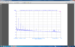
After all these I did again the measurements and I attach the new and correct FFT plots. All plots are “un-weighted” and the smoothing window that used is the “Kaiser 6”.
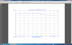
In the first is shown the THD, THD+N, SNR, Noise level with the output of amplifier at 1Wrms/8Ω. In the second plot are shown the same parameters at the full output power, here you can make a comparison with the previous FFT plot of how much better are the numbers! In the third plot is presented the bandwidth at 1Wrms/8Ω which is taken using as stimulus white noise insted sinus sweep (like does make all good people). I also attach the plots in pdf for a better view.
I hope the misunderstanding has now resolved and I ask again your forgiveness for the misinformation.
Hi guys, thank you so much for your kind words and for encouraging me. You are very polite!
Now, I ask to forgive me all of you because all the FFT plots I posted above are wrong. Especially I ask the forgiveness of John who financed the construction of this amplifier and probably could be afraid from your replies which are by 100% correct! Also the forgiveness of Andy Groves in who belongs this design which is also used in most of the famous Audio Note SET amplifiers.
As I refer above, my PC was damaged and I replaced almost everything inside as well the OS in Windows 7 Professional – 64bit. So I had to reactivate all applications included the Virtins MI 3.2 Pro FFT which I had to use 1 year ago and I forgot almost everything about it. My sound card also installed with upgraded drivers and Windows 7 allocated their own ASIO driver on it. So MI 3.2 was working with wrong ASIO driver (the correct is the “C-Media Oxygen” and I find it today when I did again set-up of FFT software. The Signal Generator of MI 3.2 takes the control of both sound card and windows mixer, based on the ASIO driver so it is mandatory to be the correct one. I also did the FFT analyses at the full output power of amplifier just before clipping. After your replies, especially of “Glowsignal” who addressed me in the site of P. Millet, I saw that the measurement method is different. I saw it and in other sites. Normally the amplifier is tested at 1Wrms/8Ω which is the reference point for the FFT analysis and some time the THD in max power is referred just for the record.
After all these I did again the measurements and I attach the new and correct FFT plots. All plots are “un-weighted” and the smoothing window that used is the “Kaiser 6”.
In the first is shown the THD, THD+N, SNR, Noise level with the output of amplifier at 1Wrms/8Ω. In the second plot are shown the same parameters at the full output power, here you can make a comparison with the previous FFT plot of how much better are the numbers! In the third plot is presented the bandwidth at 1Wrms/8Ω which is taken using as stimulus white noise insted sinus sweep (like does make all good people). I also attach the plots in pdf for a better view.
I hope the misunderstanding has now resolved and I ask again your forgiveness for the misinformation.
Attachments

Last edited:
Thank you so much fellow Δημητρη for your kind words!Nice build congratulations !! I think that you have high levels of distortion too , IMO the reason is that you have one stage of voltage gain using the EF86 in pentode mode and you want to obtain the maximum gain from it without any kind of feedback local or global .
Yes, you were right about distortion level. The first FFT analysis i did was wrong due to wrong set-up of MI Pro 3.2 FFT software as i explained in my previous post. Hope now the numbers are good for a SET power amplifier without any feedback. As i refer in previous post "no global feedback" was a demand of John who is the finance of this project.
Regarding changes arround EF86, what can i do? It is not mine design, it is an exact copy of the original design of Andy Groves (Audio Note) for the "Glass House 300Bse" amplifier which received a lot of positive reviews. The same scheme is also used in all Audio Note commercial monoblocks. A single pentode (6SH7) in input drives directly (AC coupled) a pair of 300B in output. In few models Audio Note uses an interstage transformer. Most of these monoblocks have received lot of positive reviews and some awards. By sure i am above all a technician and not a "Golden Ears"
 . I can perceive very well what mentioned by you and Glowsignal, i am solid state guy. That is my first and probably the last tube amplifier that i built. For my own research and use, i have in my plans to build a "true symmetrical" BJT power amplifier (it is the latest style in SS, Nelson Pass has allready built enough such type amplifiers) and a digitally controlled preamplifier (PGA2310 + LME49720). I have stocked all parts needed enough months ago, but i am involved with these tube projects (it follows a preamplifier and a voltage stabilizer) because... money.
Thank you again.
Φωτης
Thank you so much Chris for your positive comments. You are very kind. Yes, these turrets you use are refered as "Collar Sleeves" from Farnell and i used the same term.You do some very nice looking and detailted work. I like to use "turrets". You call them "collar sleeves" but they look the same. I've never liked PCBs for tube equipment but "point to point" looks like a mess (when I do it.) so I like to compromise. Here is a photo of a power supply board I made for a stereo amp. It slightly resembles your method but I can make these in 30 minutes start to finish, literally. It is very fast. I draw the design on the fiberglass with a pencil them walk to the drill press, install the turrets then solder the parts.
https://www.dropbox.com/sh/vspqq9fbsptuoq9/6xIQUgVkhj
The box and chassis is a first "test fit". Neither is complete yet. But the PS board is done and will fit inside the chassis. Notice this board is a "wiring board" but it is just not a "printed wiring board". I use real wire.
I can perceive your "hate" to PCBs, i also hate them when i have to construct one. I made a small amateurish lab in home to produce samples. PCBs are a big trouble from the design up to the finish of actual model. Fortunatelly these presensitized PCBs have resolved the 50% of our problem enough years ago. But since i am involved exclusivelly with solid state devices 30 years ago (many of them are monster PA power amplifiers in the range of 2 X 1000W/2Ω, some other are digital projects using nicrocontroller) PCBs are necessary for such projects because their complexity. Tube projects are by far most simple in hooking-up. Believe me that to design and to construct a PCB instead a mess-up with cables is simplest for me, it is the power of habit. In addition, this SET amplifier is enough complex as it includes 3 voltage regulators for the DC stabilization of voltage for the heaters, and a separate and enough complex circuit for the DC supply of 5687 tube. Regarding PCBs, are not bad for tube projects. Instead wires they offer copper tracks. If are tinned with a thick layer of solder, then can sustain tenths of amperes. For the concrette amplifier, except PCBs there is need for 12 meters of single wire for hooking-up PCBs between them, transformers, choke etc.
I saw the pictures of your project, iit looks very nice and i wish you success.
Fotis
Γεια σου Φωτη you're welcome , you can make a very simple change in the EF86 stage by just removing the bypass cathode capacitor , this will reduce the gain of the amp ( Ι hope this will not be a problem ) but will add some local feedback there ( cathode current feedback ) and the sound of the amp will be cleaner than before .Thank you so much fellow Δημητρη for your kind words!
Yes, you were right about distortion level. The first FFT analysis i did was wrong due to wrong set-up of MI Pro 3.2 FFT software as i explained in my previous post. Hope now the numbers are good for a SET power amplifier without any feedback. As i refer in previous post "no global feedback" was a demand of John who is the finance of this project.
Regarding changes arround EF86, what can i do? It is not mine design, it is an exact copy of the original design of Andy Groves (Audio Note) for the "Glass House 300Bse" amplifier which received a lot of positive reviews. The same scheme is also used in all Audio Note commercial monoblocks. A single pentode (6SH7) in input drives directly (AC coupled) a pair of 300B in output. In few models Audio Note uses an interstage transformer. Most of these monoblocks have received lot of positive reviews and some awards. By sure i am above all a technician and not a "Golden Ears"
Thank you again.
Φωτης
Best luck , Δημητρης .
Hi Dimitris, thank you so much for the advice. By chance i did what you suggest 1 month ago, but just for reduction of input sensitivity because the given high nominal 0.4Vrms for full output power of this SET amplifier. I placed a question here in this forum, but in other thread of how i can reduce it, say at 1.2Vrms for full output power. A member told me the same like you. Indeed the sensitivity had reduced but the amplifier after a while presented instability issues. I did a research and i find the instabillity at the plate of EF86. Later on, i don't remember exactly where i read it, i located the problem which is directly related with the bypass cap. This cap serves as a channel for any AC component from cathode to the GND which can affects the input side of EF86 (?) if i remember well. Or the inverse? By any way that i remember well is that the bypass cap serves to prevent any affection of EF86 input from its output. And that proved in my case. So i placed again the 220μF electrolytic cap in its place and everything went OK again. I had no idea of that you say - if i understand well - that the cathode bypass cap affects the linearity (?) of EF86. Please correct me if i am wrong.Γεια σου Φωτη you're welcome , you can make a very simple change in the EF86 stage by just removing the bypass cathode capacitor , this will reduce the gain of the amp ( Ι hope this will not be a problem ) but will add some local feedback there ( cathode current feedback ) and the sound of the amp will be cleaner than before .
Best luck , Δημητρης .
By any way, thank you so much again for your interest about my effort. I really appreciate it very much, as well this of Glowsignal and ChrisA. Unfortunatelly there is very few people here in tubes forum with good technical formation. I am not used in such situation on the solid state forum.
Καλο απογευμα
Φωτης
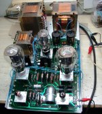
Amplifier picture during tests
And here is a picture in which you can see the off-hand wiring of amplifier that i did for the tests. I ordered UPOCC Silver wire and teflon tubing, but i received them this Friday, so i had no other solution for making the tests for so long time. I hooked-up all PCBs and parts between them with common electrical NYA 1mm wire. I've also checked the place of output trafo (in the right side) if is good. Indeed, the "T" place against the power trafo (left side) proved quite good. I haven't any EMI infection of output trafo from the Mains one. The total noise (HUM and HISS) i measured under such conditions is -52dBV (about 2mVrms) as is shown and in the above FFT plots. I hope that will be reduced further after the completion of mild steel trafo covers and the copper top plates.
And here is a picture in which you can see the off-hand wiring of amplifier that i did for the tests. I ordered UPOCC Silver wire and teflon tubing, but i received them this Friday, so i had no other solution for making the tests for so long time. I hooked-up all PCBs and parts between them with common electrical NYA 1mm wire. I've also checked the place of output trafo (in the right side) if is good. Indeed, the "T" place against the power trafo (left side) proved quite good. I haven't any EMI infection of output trafo from the Mains one. The total noise (HUM and HISS) i measured under such conditions is -52dBV (about 2mVrms) as is shown and in the above FFT plots. I hope that will be reduced further after the completion of mild steel trafo covers and the copper top plates.
Attachments
Hi!The way to reduce your input sensitivity and keep the EF86 stable is to connect the EF86 as triode. It is pretty easy to try, g2 connects to the anode via a resistor of around 100Ω-1kΩ (not very critical), G3 remains as is. Cathode bypass capacitor stays.
Will Triode-mode on the EF86 affect sound quality?
Best regards
The way to reduce your input sensitivity and keep the EF86 stable is to connect the EF86 as triode. It is pretty easy to try, g2 connects to the anode via a resistor of around 100Ω-1kΩ (not very critical), G3 remains as is. Cathode bypass capacitor stays.
Hi fellow Κωστη. Thank you so much for your interest, i really appreciate it.
I decided long time ago to keep the original 0.4mV input sensitivity of EF86 because it matches with the output level of most commercial tube preamplifiers. The finance of this amplifier John, has already a such tube preamplifier and no intention to use in the future a solid state preamplifier. I tried this SET amplifier in audition tests with my MD player (1Vrms max output) directly connected in input without any audible overdrive problem though.
By any way, thank you again for the suggestion.
Φωτης
Last edited:
Γειά σου Φώτιος!
I am in the impression that commercial tube preamplifiers have too much gain, but I don't know cause all my stereo is DIY. I have built a passive pre and I cannot overdrive my final with 0.7 V RMS sensitivity. So if you re OK or not, depends on the gain of the preamplifier.
Join, linearity depends on the operating point, in general it is easier to choose a linear operation point for a triode, but you have to be much more careful for a pentode (unpublished G2 operating points, narrow "sweet spot"). So, a (kinda) random guess would be that it could be more linear. More examination is necessary.
Hi!
Will Triode-mode on the EF86 affect sound quality?
Best regards
Yes. Many people like the it. But if the amp has NFB, triode mode will reduce the open loop gain and you might want a different feedback network.
The best solution is a switch and then you can have it both ways. I think triode mode sounds the best but you can't get much power from a EF86 used as a triode. But for low "bedroom" volume listening levels you might switch to triode and then use the pentode mode for when higher power is desired. For the price os a toggle switch you get, in effect, two amplifiers.
But do NOT ever flip the triode/pentode switch with power applied. Put that switch on the rear panel or even inside the chassis. Operating it with power and signal applied can blow the output transformers by introducing a strong transient.
Hello JoinHi!
Will Triode-mode on the EF86 affect sound quality?
Best regards
I am sure that the sound quality will be affected. If you look at the datasheet of EF86 (this of Philips is very detailed) with the given voltage values of anode and cathode EF86 has a voltage gain Av=175. If it is connected as triode its voltage gain will be reduced signifficantly. From those i understand, there is a choice between two things:
1) Hi Voltage gain, high input sensitivity, better bandwidth, more noise
2) Low voltage gain, lower input sensitivity, restricted bandwidth, less noise.
By any way the sound colloration will be changed. Andy Groves (designer of this circuit) uses in Audio Note SET amplifier kits a simillar tube the 6SH7. In the one named "Legend monoblock" he uses the pentode 6SH7 connected as pentode which drives directly (in AC coupling mode) the two output 300Bs like in the current SET amplifier. In the other model "Interstage monoblock" the 6SH7 is connected as triode but it drives the output 300Bs thru a very expensive interstage transformer, so 6SH7 anode is simply loaded with the primary winding of transformer.
Both versions present their own nice sound character. Please take a look on reviews.
And at the end Andy knows some better from us the issue of connecting a pentode as pentode or as triode accordind to the instance.
Hello Φωτη , you are very kind , as I said before in other thread I never have problem of instability when using an unbypassed common cathode stage , either in power amp or in preamp , maby you have a problem elsewere like the layout of the PCB or the power supply .Indeed the sensitivity had reduced but the amplifier after a while presented instability issues. I did a research and i find the instabillity at the plate of EF86. Later on, i don't remember exactly where i read it, i located the problem which is directly related with the bypass cap. This cap serves as a channel for any AC component from cathode to the GND which can affects the input side of EF86 (?) if i remember well. Or the inverse? By any way that i remember well is that the bypass cap serves to prevent any affection of EF86 input from its output. And that proved in my case. So i placed again the 220μF electrolytic cap in its place and everything went OK again. I had no idea of that you say - if i understand well - that the cathode bypass cap affects the linearity (?) of EF86. Please correct me if i am wrong.
By any way, thank you so much again for your interest about my effort. I really appreciate it very much,
Καλο απογευμα
Φωτης
The cathode bypass cap increase the gain therefore the distortion .
I have to make a question:
In the current amplifier, there is a pentode EF86 connected as pentode in input. I know that triodes have some better linearity compared to pentodes and also that a very popular scheme used in input are two single triodes or one double triode cascaded.
In this amplifier there is also a double triode the 5687 conected in common cathode mode (i.e. its Av = 1) that isolates the EF86 from the output 300Bs, or, with other words, that this double triode practically drives the output 300Bs. Or, that this double triode is an impedance translator, it converts the relativelly high output impedance of the sensitive EF86 to a lower impedance that can drives comfortably the relativelly heavy load of the two paralleled grids of output 300Bs.
Is there any case this 5687 to add a signifficant colloration in the total sound of amplifier? And what kind could be this colloration?
What do you think about?
Thank you
Hello Fotios
First of all, the second stage configuration is called "cathode follower". Av is less than one, usually around 0.9
It has a high input impedance and a low output impedance. It operates under 100% local feedback, so it is unlikely, if correcty designed, to add distortion. If it is driven into clipping, you get a signal that softly clips one side of the wave.
You should draw the loadline for 2 5687 in parallel, loaded with 33K//33K, at your operating points, and see how much voltage peaks it can handle before clipping, and decide if it is OK.
Thanks a lot Κωστη for the "well focused" technical comments. You are very kind and an expert!Hello Fotios
First of all, the second stage configuration is called "cathode follower". Av is less than one, usually around 0.9
It has a high input impedance and a low output impedance. It operates under 100% local feedback, so it is unlikely, if correcty designed, to add distortion. If it is driven into clipping, you get a signal that softly clips one side of the wave.
You should draw the loadline for 2 5687 in parallel, loaded with 33K//33K, at your operating points, and see how much voltage peaks it can handle before clipping, and decide if it is OK.
You are right, sorry for the mistake "common cathode", was to late in the night when i wrote the post
. Yes, it is like the driver transistors configured as emitter followers in SS amplifiers which simply serves as buffers for the high output impedance of VAS transistor. I haven't experience with tubes so your confirmation that 5687 does not add distortion was precious. You are also right on this you said about clipping of one side of sinus. I have seen it in my DSO allways and i don't knew from where is caused this "asymmetrical" clipping.
Thank you fellow for enlighten me and have a nice week!
Φωτης
My workstasion PC is again in order repaired and upgraded with new AeroCool PS, Asus M/B, Intel i3 3.4G CPU and 8GB RAM!
Well, as i promised i attach the actual schematics with valid voltage marked on each point. Tommorow i will make the FFT analysis of amplifier and i will post the results.
Fotis
The Pete millett soundcard measurement interface is quite good and prevents accidents like this, I can highly recommend it, been using it for two years now.
http://www.diyaudio.com/forums/tubes-valves/155405-test-measurement-interface-soundcard.html
Best regards,
Peter
Thank you so much Peter!The Pete millett soundcard measurement interface is quite good and prevents accidents like this, I can highly recommend it, been using it for two years now.
http://www.diyaudio.com/forums/tubes-valves/155405-test-measurement-interface-soundcard.html
Best regards,
Peter
That is a very good sound card interface! I will try it imediatelly!Fotis
- Status
- This old topic is closed. If you want to reopen this topic, contact a moderator using the "Report Post" button.
- Home
- Amplifiers
- Tubes / Valves
- My first tube project !