Hi Al,
What about a few more mods as on the attached sketches.
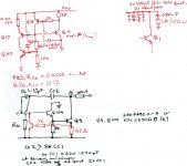
Changing Q9 into a Darlington type VAS gives more power to OPS, improves local feedback and functioning of the current source Q11. Q110 and R110 have been added to ensure that Q9 is not blown when short circuit protection is activated.
Two pole compensation further improves NFB at higher frequencies around that stage. Rcc could be between 1k and 10k. Randy Sloan uses often 1k. CC2 must be at the very minimum twice the value of CC1 but Rnady favours 5 times the value or even more. Your tested CC1 value of 47pF stays, only CC2 has to be recalculated and tested starting with say 270pF or somewhat higher and going down to no less than 2xCC1 according to Douglas Self.
Changes around Q11, Q18,Q17 are to ensure higher and symmetric Slew Rates (problem with lower positive SRs is alleviated) and also require the reduction of R26,R27 to 12ohms (Stochino uses 5ohms resistors but his amp is much faster and has somewhat different configuration). Input dif pair emitter resistors may need to be increased to say 220ohm. You may experiment with their values as well as Rcc and Cs values. Addition of Q117 improves distortion characteristics (Douglas Self’s invention). Dif pair would also benefit by using high Beta (Hfe) low noise transistors such as 2SA970BL. It might also be worth replacing C14 and D14 with high quality bipolar from Black Gate or ES 50V Nichicon or ELNA plus 100-220nF/100V.
Final additions to are filtering caps attached to the output stage trannies. Adding fast 2x470uF/100V (Black Gate, Nichicon KZ or FG) with 2x100nF/100V polypropylene improves transient performance of the output while the addition of 680nF + 1ohm (both non-inductive) is the invention of prof.Otala. It substantially reduces the effect of PS caps inner inductance on the circuit.
What do you think?
Cheers,
What about a few more mods as on the attached sketches.
Changing Q9 into a Darlington type VAS gives more power to OPS, improves local feedback and functioning of the current source Q11. Q110 and R110 have been added to ensure that Q9 is not blown when short circuit protection is activated.
Two pole compensation further improves NFB at higher frequencies around that stage. Rcc could be between 1k and 10k. Randy Sloan uses often 1k. CC2 must be at the very minimum twice the value of CC1 but Rnady favours 5 times the value or even more. Your tested CC1 value of 47pF stays, only CC2 has to be recalculated and tested starting with say 270pF or somewhat higher and going down to no less than 2xCC1 according to Douglas Self.
Changes around Q11, Q18,Q17 are to ensure higher and symmetric Slew Rates (problem with lower positive SRs is alleviated) and also require the reduction of R26,R27 to 12ohms (Stochino uses 5ohms resistors but his amp is much faster and has somewhat different configuration). Input dif pair emitter resistors may need to be increased to say 220ohm. You may experiment with their values as well as Rcc and Cs values. Addition of Q117 improves distortion characteristics (Douglas Self’s invention). Dif pair would also benefit by using high Beta (Hfe) low noise transistors such as 2SA970BL. It might also be worth replacing C14 and D14 with high quality bipolar from Black Gate or ES 50V Nichicon or ELNA plus 100-220nF/100V.
Final additions to are filtering caps attached to the output stage trannies. Adding fast 2x470uF/100V (Black Gate, Nichicon KZ or FG) with 2x100nF/100V polypropylene improves transient performance of the output while the addition of 680nF + 1ohm (both non-inductive) is the invention of prof.Otala. It substantially reduces the effect of PS caps inner inductance on the circuit.
What do you think?
Cheers,
Attachments
Hello Al,
Your ringing pic looks pretty good. After all the fiddling, I would install a 1K/470pF input filter ( same 330KHz as your feedback rolloff) and you'll have a cleaner ring as the VHF are filtered out. BW will then be 200KHz.
Now, still keeping it simple, I would try taking the 47pF off the Vas and putting 10p instead just to define the pole and then 47p from Vas collector to the feedback point (base of Q16). Check the sq wave performance and lower THD (if you can). You may have to remove the 22pF feedback C for this.
Does it thump at turn on/off? You can probably dethump it by lagging Q11 base with a RC to supply (470/22uF)
And I would change the 15K's in the protection cct to 22K min to combat premature turn on at large Vswing.
Hope this helps.
Hi januz,
Thanks for your suggestions and advice. When I built the prototype I included two pole compensation, and a Darlington type VAS. But as you well know what really matters is not how well the amplifier measures but how it sounds. I just wanted to keep the design simple, and after hours of listening with and without the additional components and comparing against some fine amplifiers I decided to go with the current design. I think it measures very well, and sounds great. I agree that using some high end quality bipolar for C14 could improve the sound without adding to much to the cost. Thanks again.
Regards,
Al
first amp - slew rate mods
Hi Al,
Darlington VAS alone may subjectively sound worse but you may need it if you did all the other mods. THD may not improve dramatically but the aim of these mods was to improve slew rates and make them symmetrical. At the moment, I’m guessing, but an amp with such topology as yours would have positive slew rate about 40% down the negative one. With the suggested mods and fine tuning of associated resistor and cap values negative slew rate may increase by 30% or even more while the positive slew rate would rise to match the negative (actually come very close to it). Bias may also need to be increased substantially but as a result of all that crossover distortions, switching distortions and TIMs should notably go down and that is very audible. The choice of transistors becomes important. Both Q9 and Q11 should be chosen especially for lowest possible inner capacitances (especially on the collector size even in your circuit), Q11 should have high hFe and you might find that low capacitance FET could work better as Q11 – possibly even in your circuit.
I remember when in the late 1970s I had an opportunity to listen to Electrocompaniet amps in Holland and Germany. I was surprised how detailed was their sound image. These were built following Otala’s concept of what Hi-Fi amps should do and how and that involved minimization of all sorts of distortions with the emphasis on the dynamic ones. Speed and wide bandwidth were essential components of those designs. I do not think any other amp could match up to these in those times – certainly none of those I listened to and I listened to many. Then in mid 1980s I built my first fast for those times (over 75V/us) amp with lateral Mosfets designed to minimise TIMs, crossover and switching distortions. It was not as good as Electrocompaniet (I used rather ordinary components) but was substantially better than most amps I heard in Perth on Hi-Fi (or Audio-electronic) expos we used to have those times. I must admit that Australia and especially Perth are not the best places to look for really top HiFi equipment but then we had relatively more of those goodies available locally.
At present I’m building Stochino’s amp with some part upgrades. The moment I saw it I was attracted to it expecting all the goodies associated with its design principles. It is a very fast amp (over +/-300V/us) and although I haven’t heard it yet those who did claim that it is very difficult to match. You may check entries on Stochino on this site. The topology you have, if tweaked to the max, probably could not go much beyond +/-70-80V/us (I’m guessing) but even that should make a notable difference. Maybe one day you will be tempted to test such mods in your free time or go straight for much faster topologies aiming to minimise all those dynamic nasties.
Cheers,
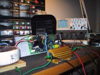
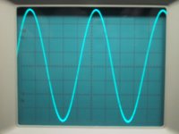
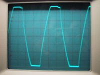
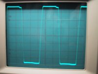
Just wanted follow up from a previous post on how well the amplifier handles with peak power. So here are some pics of the RTS100 at maximum power at 1khz and 20khz into 4 ohm load at 29.9Vrms 42V peak. You'll see from the pics that it held up really well. The amplifier triangulates at full power into a 4 ohm load at about 85Khz. I also cranked the rails to +/-60V and ran the amplifier into 4 ohm load for nearly 20 minutes at 1Khz at 32Vrms, and again it held like a champ. The load was sizzling but I could actually touch the heat sink for about 3 seconds without burning my hand.
BTW the four amplifiers are sitting on my bench collecting dust waiting for whoever wants them. I'm nearly giving these things away so please email me if your interested at alsaudiokits@yahoo.com.
The first pic is of my test setup, with the amp running at full power into a 4 ohm load at 1Khz.
BTW the four amplifiers are sitting on my bench collecting dust waiting for whoever wants them. I'm nearly giving these things away so please email me if your interested at alsaudiokits@yahoo.com.
The first pic is of my test setup, with the amp running at full power into a 4 ohm load at 1Khz.
Attachments
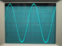
AAK said:Here's a pic of the amplifier output with a 4 ohm load at 29.9Vrms 42V peak at 20Khz.
Hi
This looks good. It looks like the high hfe of both the output and the driver transistors were sufficient to produce the required output current. I have checked your driver transistors and they have good spec (high hfe and Ft) for medium power bjt. In fact, I think I may used them in lieu of 2N5415/2N3440.
Hey everyone. Just wanted to announce my website which is still under construction and needs a lot work. Starting an operation of this sort over the internet is a very difficult undertaking. But I'm doing this because of my passion for music and DIY Audio. If your looking for an amplifier kit, I ask you to put your trust in me, you'll will not be disappointed. Keep yours eyes open for the RTH100 Hybrid Amp Kit which should be available soon, and my Other Projects section which I'll be updating soon with more details on past projects, including schematics. You can find my website at, you guessed it, www.alsaudiokits.com.
Best regards,
Al
Best regards,
Al
Banned
Joined 2002
AAK said:
HOw much is your second dac ? I like it. ? Can you pm me please.
Jason
Best of luck!
Hey Al,
That's great. The world needs more DIY resources like your new website. I hope the endeavor pays off for you.
Have you also considered packaging the kits as just boards, boms and instructions? (ala Rod Elliot) That's the way I like to DIY. Buying a fully assembled kit, in my opinion, is like picking thornless blackberries. If there's no pain/blood during the picking, then the pie isn't nearly as satisfying afterwards.
Seriously, I enjoy sourcing the components, populating the boards, and all the other foibles you can imagine that go along with that. The part I LEAST enjoy is sourcing or building the chassis -- trying to make it look good. And with your kits, that's the only thing I'd be left with.
Cheers and thanks again.
TAJ
To Al : Pic of 20 kHz sinewawe nothing tell about quality of amp, 'cos it know every amp and important parametres are not visible on scope in this case. Can you show us pics by 1 dB below clipping, by full power and by clipping ( 1 dB and 3 dB over full power ) at this frequency ? ")
- Status
- This old topic is closed. If you want to reopen this topic, contact a moderator using the "Report Post" button.
- Home
- Amplifiers
- Solid State
- My first solid state amp