That could give you more current handling but it won't change the voltage. Then you run into the trouble of current sharing between devices.
Sorry my typo I wanna say series, thanks Frank.
Just know that you are using an LED for an unintended purpose. The manufacturer did not intend that it be used as a biasing device for the cathode of a vacuum tube. It's up to you, Mr. Engineer, to figure that out for yourself since the data sheets for LED's are not going to be much help. LED's are intended to be illumination devices. The fact that they can work as cathode bias devices also is more a freak of nature than an intended consequence. So, that's why you have to think hard about how you use them.
The datasheets actually do give you the info you need for that application. The slope of the If vs Vf curve at the operating current yields the impedance and the Vf.
For low current circuits, there's an easy (one resistor) work-around that I've discussed many times and is shown in "Valve Amplifiers" 4th ed., figure 3.26. This retains the great virtue of LEDs for biasing, essentially instantaneous recovery from overload.
The one actual limitation is indeed low voltages (<1.2V or so).
The datasheets actually do give you the info you need for that application. The slope of the If vs Vf curve at the operating current yields the impedance and the Vf.
For low current circuits, there's an easy (one resistor) work-around that I've discussed many times and is shown in "Valve Amplifiers" 4th ed., figure 3.26. This retains the great virtue of LEDs for biasing, essentially instantaneous recovery from overload.
The one actual limitation is indeed low voltages (<1.2V or so).
I know they provide those curves. What happens when you exceed the rated current for the device? What happens to the curves when the device is heated up because it's attached to a red hot cathode? How do you derated it?
Like I said, these devices were not intended for this use. You're on your own if you want to use them this way.
What happens when you exceed the rated current for the device? What happens to the curves when the device is heated up because it's attached to a red hot cathode?
In order:
1. They burn out. If you exceed maximum current or voltage for any electronic component, they tend to burn out.
2. I am unable to get inside the envelopes of my tubes to try your suggestion. For general thermal derating information, it's on the datasheet. See, for example, Data Sheet - HLMP-Pxxx, HLMP-Qxxx, HLMP-6xxx, HLMP-70xx Series Subminiature LED Lamps (234 KB) for the curves for the HLMP series that I use most often. Figure 5 shows thermal derating.
2. I am unable to get inside the envelopes of my tubes to try your suggestion. For general thermal derating information, it's on the datasheet. See, for example, Data Sheet - HLMP-Pxxx, HLMP-Qxxx, HLMP-6xxx, HLMP-70xx Series Subminiature LED Lamps (234 KB) for the curves for the HLMP series that I use most often. Figure 5 shows thermal derating.
You do not understand what I am saying. You do not have to "get inside" of the tube and you know it. The red hot cathode is connected by a wire to the pin on the tube. It's going to get hot and heat up anything attached thereto, including an LED. Why is this so difficult for you to understand?
Not only that, but you miss my point entirely, which is that when you use a device for an unintended purpose, it's up to you to determine if it's suitable or not. Obviously, you've made some effort in that direction, which is fine. So, I have no argument with using LED's for biasing cathodes, just that there are considerations to be thought about that may or may not be readily available.
Last edited:
Maybe because I've actually built a few amps and have some experience. The wires from the socket pins connected to cathodes of tubes don't get significantly hot. If they do, you used a ridiculously thin wire, and I mean ridiculously thin.
The LED datasheet shows a max operating temp of 100C. Frankly, I've never seen anything close to that on a circuit board or under-chassis. It may be theoretically possible to construct something where all the components are bathed in a 110C environment, but that would take some creativity, extreme stupidity, or both.
Follow the datasheet and all will work as planned.
Maybe because I've actually built a few amps and have some experience. The wires from the socket pins connected to cathodes of tubes don't get significantly hot. If they do, you used a ridiculously thin wire, and I mean ridiculously thin.
The LED datasheet shows a max operating temp of 100C. Frankly, I've never seen anything close to that on a circuit board or under-chassis. It may be theoretically possible to construct something where all the components are bathed in a 110C environment, but that would take some creativity, extreme stupidity, or both.
Follow the datasheet and all will work as planned.
Wow, you really like to taunt me don't you? What's that about? Why do you assume I have not built and rebuilt a lot of amplifiers and other gear in my lifetime? Where do you get off saying that? Why are you so rude to me? You don't know me and you don't know what I've done.
You've never touched the chassis of an ST-70? I have. They get HOT! So, no, maybe I DO know what I'm talking about after all.
You've never touched the chassis of an ST-70? I have. They get HOT!
Yes, they can reach 60C or so if the ventilation isn't good. Perfectly safe for LEDs. In a preamp application (the topic of this thread), the temperatures are generally quite a bit lower.
Coincidentally, the first time I used LEDs for biasing was in 1978 on a... ST-70. The creative guy who put me on to that idea was Ike Eisenson, someone badly missed on the audio scene.
Hi,
A brilliant mind indeed.
Preamp, input stages, that's where they belong. Does away with the dreaded bypass caps and avoids this equally dreaded blocking distortion when used properly.
And, since they glow a bit I don't even mind their solid state pedigree all that much....
Ciao,
The creative guy who put me on to that idea was Ike Eisenson, someone badly missed on the audio scene.
A brilliant mind indeed.
In a preamp application (the topic of this thread), the temperatures are generally quite a bit lower.
Preamp, input stages, that's where they belong. Does away with the dreaded bypass caps and avoids this equally dreaded blocking distortion when used properly.
And, since they glow a bit I don't even mind their solid state pedigree all that much....
Ciao,
Hi there,
Luckily I have found this thread and carefully went through it - I am trying to re-build one of these myself and found very good ideas and solutions. Will be thankful to find out the final schematics in order to compare with my findings.
Thanks to everyone sharing his experience.
Best regards,
Ignat
Hei everyone! It was almost a year ago i wrote her and this preamp have given me superb sound ever since then.
Very happy and many people have listened to it and quotes like "clean n transparent with very good detail" have been said!
2-3 months ago the main fuse blew and i replaced it and it have been working good till about 2 weeks ago when again the fuse broke and when i replace it blows again, i did some checking and found one of the electrolytic caps to (vishay 450v/150uf) to measure 0.000 while the other one measures as before 142uf... Hmmmm replaced it and still same problem but atleast the fuse don't blow so violent that it's "black" anymore.
I hope it's not the PT. Anyway, this is a nice project and very very good sounding!
Hi Max and everyone following this thread,
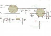
Based on your experience and the suggestions of the guys around I have modded my chinese preamp very similar to yours and have some questions you can eventually help --
- please have a look at my schema and suggest ideas /esp choke and resistor's values in the PS part/
- shall I ground the mid pin of the triodes ??
- how to decrease the gain /too big at the moment/ ??
Some of my ideas are to go for smaller value of the cathode res - say 180R like you and get a bit higher current there /now around 4 mA - depends on the tubes I put/, to apply a choke replacing the first 1.5K resistor in the PS, to install a 50K motorised pot after the final cap in order to attenuate the output volume, and at the end to get all the stuff into some metal box /now laying around on a piece of laminate flooring.
Any comment is welcome,
Thanks,
Attachments
- Status
- This old topic is closed. If you want to reopen this topic, contact a moderator using the "Report Post" button.
- Home
- Amplifiers
- Tubes / Valves
- My first preamp with tubes