Hi,
After lurking around in this forum for years, I'm tempted to build my own LM1875 amp.
The amp would be powered by 180VA 18-18V CT Transformer.
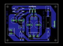
Here the schematic and the layout.
I adopted ESP and Daniel design, and AndrewT suggestions on others thread.
Suggestions and comments are welcome. before I etch the PCB.
Many thanks,
-- Peter
After lurking around in this forum for years, I'm tempted to build my own LM1875 amp.
The amp would be powered by 180VA 18-18V CT Transformer.
Here the schematic and the layout.
I adopted ESP and Daniel design, and AndrewT suggestions on others thread.
Suggestions and comments are welcome. before I etch the PCB.
Many thanks,
-- Peter
Attachments
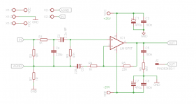
One issue I have is your connecting the small signal ground at the point where the output Zobel connects to ground and this goes through a trace to the main ground area where the bypass capacitors are. At high frequencies, heavy enough current can flow in the Zobel and cause distortion or oscillation of the amplifier. The input ground should be moved to have its own path direct to the main ground area.
Where is the output return pin?
Where is the output return pin?
What are you using for source? With my mobile phone, higher impedance loading on the output sounds better so now I aim for 200kohm minimum for my input impedance. You're currently at about 47k which you could increase.
Nice tips. It mostly will be connected to PC or laptop.
Does 200KOhm min. input impedance also apply to the PC or laptop source?
Johnr66:
Thank you for your analysis, but there is R7 to separate input ground and main ground, but if you think it's not enough, I will try to separate the ground path.
The output return will be directly connected to the Power supply star ground, Is that OK?
Regards,
-- Peter
Last edited:
Nice tips. It mostly will be connected to PC or laptop.
Does 200KOhm min. input impedance also apply to the PC or laptop source?
Johnr66:
Thank you for your analysis, but there is R7 to separate input ground and main ground, but if you think it's not enough, I will try to separate the ground path.
The output return will be directly connected to the Power supply star ground, Is that OK?
Regards,
-- Peter
A 1 ohm resistor will do very little to keep induced voltage in the ground out of the high impedance of the input.
OK on the output return.
Keep the input bias resistor as you have it or even better, at the datasheet value. Any proper line in signal will have no issues and less chance of noise if the input source goes high impedance such as its power is turned off or cable unplugged.
Hi,
After lurking around in this forum for years, I'm tempted to build my own LM1875 amp.
The amp would be powered by 180VA 18-18V CT Transformer.
Here the schematic and the layout.
I adopted ESP and Daniel design, and AndrewT suggestions on others thread.
Suggestions and comments are welcome. before I etch the PCB.
Many thanks,
-- Peter
I see a few things that I would do differently, but it's time for lunch and I'm hungry. In the mean time I recommend you take a look at this - Taming the LM3886 Chip Amplifier
Tom put a lot of good information about circuit layout and stability in there, and while it's based on the LM3886, the LM1875 is from the same chip lineage so everything still applies.
Mike
It mostly will be connected to PC or laptop.
Does 200KOhm min. input impedance also apply to the PC or laptop source?
No direct experience myself but another DIYer reported to me that his laptop sounded better after he'd done a mod I suggested which raised the input impedance of his amp.
Higher impedance inputs do have a downside and that's increased pickup of rubbish when the source isn't connected. Don't leave an input cable dangling with nothing at the far end with the amp powered and feeding a speaker, its asking for trouble when the amp input impedance is high.
Nice tips. It mostly will be connected to PC or laptop.
Does 200KOhm min. input impedance also apply to the PC or laptop source?
Laptops outputs should be designed to work with headphones (also the low power supply of computers). Most headphones have 32 Ohm. Higher ones around 600 Ohm. These are still difficult load for the sound card (usually higher impedance headphone sounds better). 10k is okay, so I think no need 200k as it may disbenefit the amp itself.
Impedance matching is a balance act between DISTORTION and POWER.
With amplifier load (LM1875) we don't care about power, we care more about distortion. 47k load impedance is a standard. Increased load will usually lower the distortion of the driving preamp, but increase (very slightly) the distortion of the amp itself...
So I don't think 47k-100k is a problem in your situation.
But then remember that most laptops output can be set to output line level or high level (for headphone) through the codec software. I believe that low level should be better for your LM1875. Or may be more noisy, you can check by yourself.
My experience with most consumer gear with 1/8" headphone jacks is that the output voltage delivered is insufficient for most line level inputs. Most of this stuff is meant for driving run of the mill 32 Ohm (or there about) earbuds. With the recording level of most music, I can turn my music player to full volume and not get loud output from the amp when set at 26db gain. Some computers may allow you to set the output for line level in the software.
When someone claims "sounds better" with such a high impedance would want me to know more details of their circuit because with properly designed equipment, this is utter nonsense.
When someone claims "sounds better" with such a high impedance would want me to know more details of their circuit because with properly designed equipment, this is utter nonsense.
with properly designed equipment,
Equipment is designed for a target impedance/resistance. It would be easy if everyone is designing from source to speaker, integrated, but we're not.
Thank you for all the inputs and suggestions, You guys awesome.
Layout had been modified, better gnd path separation, as suggested by johnr66
Will experiment with the impedance values after finishing the amp board.
I notice that ESP's LM1875 amp, project 72, have different zobel components arrangement than usual.
Single Chip 25W Amplifier (Project 72)
Is this intentional? what effects would it cause? to the work of the amp, and to the sound especially?
(my deduction is to prevent hi-pass filter forming with the speaker cable's capacitance, but why only on LM1875 circuit?)
or just only a different arrangement
Regards
Layout had been modified, better gnd path separation, as suggested by johnr66
Will experiment with the impedance values after finishing the amp board.
I notice that ESP's LM1875 amp, project 72, have different zobel components arrangement than usual.
An externally hosted image should be here but it was not working when we last tested it.
Single Chip 25W Amplifier (Project 72)
Is this intentional? what effects would it cause? to the work of the amp, and to the sound especially?
(my deduction is to prevent hi-pass filter forming with the speaker cable's capacitance, but why only on LM1875 circuit?)
or just only a different arrangement
Regards
Thank you for all the inputs and suggestions, You guys awesome.
Layout had been modified, better gnd path separation, as suggested by johnr66
Will experiment with the impedance values after finishing the amp board.
I notice that ESP's LM1875 amp, project 72, have different zobel components arrangement than usual.
Single Chip 25W Amplifier (Project 72)
Is this intentional? what effects would it cause? to the work of the amp, and to the sound especially?
(my deduction is to prevent hi-pass filter forming with the speaker cable's capacitance, but why only on LM1875 circuit?)
or just only a different arrangement
Regards
Unless Rod gave a specific reason, I'd use the datasheet values. The engineers who developed the IC likely put it through a battery of tests and came up with those values based on the results.
When someone claims "sounds better" with such a high impedance would want me to know more details of their circuit because with properly designed equipment, this is utter nonsense.
I don't have the circuit details because they're commercially available players (mainly smartphones of various makes, an old iRiver mp3 player) but the effect is consistent. Buffer the output and it sounds better in a fairly consistent way, described independently by a few listeners who I tried it out on.
Is this intentional? what effects would it cause? to the work of the amp, and to the sound especially?
(my deduction is to prevent hi-pass filter forming with the speaker cable's capacitance, but why only on LM1875 circuit?)
or just only a different arrangement
Regards
I think he tries to separate the low level signal earth from the filter and output ground. Not wise to directly connect the imput ground to the output ground.
In some cases even a 2-3 ohm is put to the input ground before connected to the "main ground" to somewhat filter it a bit more.
I don't have the circuit details because they're commercially available players (mainly smartphones of various makes, an old iRiver mp3 player) but the effect is consistent. Buffer the output and it sounds better in a fairly consistent way, described independently by a few listeners who I tried it out on.
I'll have to test this to see what is going on. An audible difference means the signal is being changed in a measurable way. I know my Sony player makes .001% THD @ 1KHz through the high impedance. I'll have to check the frequency response and THD with a normal 32 ohm load.
I'll have to test this to see what is going on. An audible difference means the signal is being changed in a measurable way.
Sure, but measurable does not necessarily mean that current measurements (for example, THD+N) are going to show a difference. I rather suspect that we need a new measurement.
I know my Sony player makes .001% THD @ 1KHz through the high impedance. I'll have to check the frequency response and THD with a normal 32 ohm load.
I suggest rather build a classA buffer with >200kohm input impedance and listen for yourself. If you can hear no improvement then you may conclude my listening and that of various of my associates is the result of placebo effects.
Unless Rod gave a specific reason, I'd use the datasheet values. The engineers who developed the IC likely put it through a battery of tests and came up with those values based on the results.
Agree, in my circuit all default components using either datasheet values or calculated values from overture_design_guide.xls spreadsheet.
I suggest rather build a classA buffer with >200kohm input impedance and listen for yourself. If you can hear no improvement then you may conclude my listening and that of various of my associates is the result of placebo effects.
IMHO, adding a buffer, would it be already making an improvement(difference)?
Would it probably be better if doing experiment on amp's input impedance values directly, to find any significant differences?
- Status
- This old topic is closed. If you want to reopen this topic, contact a moderator using the "Report Post" button.
- Home
- Amplifiers
- Chip Amps
- My First LM1875 amp