'....If you want to read Douglas Self article you may try this link:
http://paid4share.net/download.php?id=4341
Somebody is sharing, currently it works ... but nobody can know for how long ...
...."
The link doesn't work anymore !
Lineup can you email me a copy of the file ?
Thanks.
http://paid4share.net/download.php?id=4341
Somebody is sharing, currently it works ... but nobody can know for how long ...
...."
The link doesn't work anymore !
Lineup can you email me a copy of the file ?
Thanks.
Hi Lineup brother!")
I every day read the forum, but I didn't post too much, because I am busy to learn some tube and transformer theorys.
Gaborbela is my DIY friends and He built and tested a lot of amplifiers and I know His audio taste and I believe in His oppinions.
I also know that Canopus amp and it is realy a boring amp.
The first circuit He posted looks promising, but I am not a big fun of Class AB and complementer PP transistor circuits. I am an inductor maniac guy.
Yes, I promised Him to design and make the PCB in the next month, but I think someone will overtake me. Maybe you!?!
Greets:
Tyimo
Thanks a lot for the kind words!Tyimo is great guy. We have discussed a lot. But looks he is not so often around this forum now.
I every day read the forum, but I didn't post too much, because I am busy to learn some tube and transformer theorys.
Gaborbela is my DIY friends and He built and tested a lot of amplifiers and I know His audio taste and I believe in His oppinions.
I also know that Canopus amp and it is realy a boring amp.
The first circuit He posted looks promising, but I am not a big fun of Class AB and complementer PP transistor circuits. I am an inductor maniac guy.
Yes, I promised Him to design and make the PCB in the next month, but I think someone will overtake me. Maybe you!?!
Greets:
Tyimo
anatech said:Hi ferencz,
Was that Japanese schematic a commercial design? If so, who was it made by?
Thank you very much BTW.
Hi gaborbela,
The Japanese design actually looks pretty good. Those signal transistors they used are very good (classics in high end) and still available from vendors.
This little amp might make a very nice nice project. A board design would be a nice start. If the PCB is designed for normal transistors, you can still use darlingtons by shorting the E-B pads on the extra part. One board then does all. For 56V use, two outputs should be used.
Darlington transistors normally don't work as well as single parts. If the current through the driver isn't high enough, then it will not work well.
-Chris
Hi Chris,
The schematic has been scanned from an old japanese DIY-magazine. Sry, I cannot recall the magazine's name, it was long before...
As far as I know it was never been produced commercially.
ashok said:'....If you want to read Douglas Self article you may try this link:
The link doesn't work anymore! Lineup can you email me a copy of the file ?
Thanks.
Douglas Self share some knowledge, ideas on Muting Relays
and also several of his other Articles on things in Audio.
I suspected that was only one 'temporary link' made for me.
If you try one of these, you may have better luck. File is ~ 8 MB size.
link1
link2
Here is where you can find this schematic
.... and many others
http://www.audiofanatic.it/Schemi/Tipo/Stato_solido/finali/Schemi_finaliSS.html
.... and many others
http://www.audiofanatic.it/Schemi/Tipo/Stato_solido/finali/Schemi_finaliSS.html# Da 50 a 100 Watt
* 60W IRF530 part1 part2
* 65W TIP142 147
* 70W TIP35C 36C
* 70W MOS 2SK135 2SJ50
* 75W MOS MonacorPMA100
* 80W 2SC3858 2SA1494
http://www.audiofanatic.it/Schemi/Tipo/Stato_solido/finali/Schemi_finaliSS.html
Hello
Thank for you research line up !
There are some similarity some of those schematics and what I originally posted in the first post .
But because I know the amp I posted at the beginning I would like to build exactly one more time after the same schematic . Probably with better passive components (resistors , capacitors , wiring etc)
For two reason I would like to stick to that amp I know the sound of that amplifier and I was happy with .Unfortunately as a greenhorn at that time I didn't gave enough appreciation (respect) to the great sound of the amp.
I thought naively if at the first try I achieved such a great sound the let try to improve it .
I was wrong , I tried to improve the active parts and I destroyed the PC board .It was not bigger than the size of a 10x10 cm if not smaller . It used on only 1/4W resistors on it only the emitter resistors were 5W and one on the output 2W . First build was with one set power transistors after the original schematic !
The second think there are many movies how they star the movie the same way they finish it .
I found many great sounding amplifiers over these years , so I think time to me to do the same as in those movies .
In a simple sentence to finish my DIY activity were I started .
We some of us we need to learn to be satisfied with some good sounding amplifier and to settle down and enjoy the music .
That is all about or not ?!
Of course I'm not totally retire from the DIY hobby but I want spend more time enjoy listening to the music .
Greetings
homemodder said:A friend of mine build this a couple of years back and he was happy with the results. Said he found schematics somewhere on the web. Based on similar topology.
That's a pretty clever connection of the DC servo
gaborbela said:
But because I know the amp I posted at the beginning I would like to build exactly one more time after the same schematic . Probably with better passive components (resistors , capacitors , wiring etc)
For two reason I would like to stick to that amp
I know the sound of that amplifier and I was happy with .Unfortunately as a greenhorn at that time I didn't gave enough appreciation (respect) to the great sound of the amp.
........
First build was with one set power transistors after the original schematic !
The second think there are many movies how they star the movie the same way they finish it .
I found many great sounding amplifiers over these years , so I think time to me to do the same as in those movies .
In a simple sentence to finish my DIY activity were I started .
We some of us we need to learn to be satisfied with some good sounding amplifier and to settle down and enjoy the music
Of course, gabor.
This is what you should do!
Make a new version from the Original Schematic.
You have no reason to change much .. maybe a few 'better' components/details to try.
All these other versions
is for other people reading this topic, today and next year ...
They may want to try to make something like 'your' amplifier.
i ve been trying to follow
this thread but it wasnt really easy since i am quiet busy fixing some swedish mistakes ( he he he ) i welcome swedish mechanics to talk about this in private .....
gaborbela.......
i like this amp very much since i like very much simple circuits id like though to point just a couple of things
the first and most importand this is not a circuit to be done by any user since this importand information is missing (which actually i ve been screaming for 4 years now ) all amplifiers made with TIP 142 147.... bdv 66-67 bdw 83 84 and so on suffer from the """matching issue """" and eventually will fail if caution is not considered about this .....
and i dont mean the matching of transistors as we usually mean it .......but to know how the darligton is internally made and especially between the driver transistor and the output transistor ....
Meaning that depending on the order between tip 142 and tip 147 you may find serious diference on the way they work if the litle numbers down under the tip 142 and 147 are not explained so for shure and even worst it will never work properly if your tip 147 is from ST and your tip 142 is philips .....
in amplifier i made i had to use on semis mj 11015-16 just to be on the safe side ( transitors worked fine my amlifier was a joke )
so darligtons ..... no way hose !!!!!
it would be very nice if one of us used similar topology for the input and drive mosfet instead .....
........another thing that is very interesting is that many sugested use of four darligtons per board .....well i havent found any schematic in the past that might work with four darligtons ....but may be iam wrong .....
i am very excited by that cause if you use MJ11015-16 that is a 120 volt ....30A 200W or even more with MJ 11032-33 that will go to amazing 50A!!!!!! and 300w....
with a simple circuit to drive and four pairs of these outs you could easilly produce arround 200W @8R .....and almost double @4 ohms
any ideas ????? am i missing something here ????....
its been amazing all these years to watch people design and redesign amps in search of quality ,,badwidth,, slew rate BUT !!!! I would troully enjoy a permanent thread called """cheap power amps """" were afew transistors a big psu could produce a hell of a lot of power with bellow average quality .....belive me there is use for that too....
thanks people ........
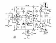
Sorry there is a mistake in the schematic
Hello
The lay out is not difficult at all but still need some experience to design it . I have no Eagle and I never ever used a PC board design software .
To replace the Darlingtons after my Experience that not not an easy point especially if you wish to keep the same sound quality .
Now when someone design the layout It would be better to go with two par output transistors .
That brought me a lot of life and improved the bass and the dynamic of the amp .
ATT.
THERE IS A MISTAKE ON THE SCHEMATIC the input resistor not2.2R is 2.2K .another think you can use a bit larger 2 or 4.7 uF capacitor on the input . But that is really matter of taste . How you like it .
Greetings
HI
We did try to substitute the BDW with MJ11015 ,16 but somehow we last the warm sound and much more . The truth is the designer said MJ Darlingtons were made for industrial use not for audio purpose . He did not said not possible to use them for audio purpose . May be is possible to modify the circuit but I do not want to end up like first time !!! How I stated there are at least 11 type Darlington circuit . That is very important to .
I also tried the TIP142 and 147 were produced in Italy but I personally I didn't like them .
The guy who design these schematic he said the firs think he chose the Darlingtos from Texas Ins. BDW83/84C and built the rest of the schematic up to drive the power transistors !???
If you like mosfet output you may take a look at the Zenquito amp .
Very similar , few parts , lateral output and J-fet input .
You can even bias that in Class A mode .
Or if you want something more simple try the ProFet .Or if you think to use vertical mosfets Pass F5 is a great amp with a few components to.
Greetings
Hello sakis
You right matching is not so simple when we talking about Darlington transistors .
But you can use with a great result even unmatched transistors to . I know I did listening to these amp a couple years , if I was not satisfied with the sound I would not think to build it again . I have some great sounding amp like AlephX ,Aleph2, Hiraga Class A and so on . But I want something different.
If you read at the ESP site 101 project even Rode said matching the outputs it is not so important .Of course it would improve the sound if you can do match them! You can use one pair output transistor with lower voltage to . To match PNP to NPN not many designer do or advise that .
Yes you right there are many different Darlington circuit in one case .
That is the main reason I want to stick with the original power transistors , and both PNP and NPN must be produced by the same company .That is a min. requirement here .
The rest of the transistors we can match easily .
Thanks for the warning.
For example in many electronic store they sat TIP142 &147 = BDW83C & BDW84C . That is not totally true , if you have a ECG catalog you can look them up and you can see it is not equal the two type of transistor .
Or you can even check the data of the transistors on the net .
The main reason I prefer to stick to the transistor the circuit was design for . And how you wrote the the complementary pairs must be produced by the same company at least .
Thanks for your comment . It is very useful to all of those who plan to give a try to these amp .
The schematic was downloaded more than 900 times so may be we will see some amplifiers to I hope .
We can find a lot of schematic with mosfet , bipolar, tubes but not many uses Darlington transistors .
The engineers who design the Darlington transistors into one case they had some purpose with , it is for a reason what I want to write .
Greetings
Hi gaborbela,
This is the only way to do things. Look at the exact device and think about the true specifications.
-Chris
ECG /NTE are a waste of time. There are enough errors in those books to begin with. Don't bother to try using those devices.For example in many electronic store they sat TIP142 &147 = BDW83C & BDW84C . That is not totally true , if you have a ECG catalog you can look them up and you can see it is not equal the two type of transistor .
Yes!!!Or you can even check the data of the transistors on the net .
This is the only way to do things. Look at the exact device and think about the true specifications.
-Chris
Hello anatech
Thank for your comment , most of the time because is much faster to open the book than turn on the computer I check in a ECG Philips book.( A couple time I get spooked because I trusted in the catalog )
But if the transistor data very important like in these case I will usually double check on the net .(I did paid for my mistakes ,Usually the stores does not take back the transistors even if I didn't touch them.)
In a short sentence before I buy or order transistors I do check on the net now . How you wrote that is for sure .
ECG most of the time give just 50% info or less what we really need to know .
Sometimes a 30V transistor they put in the same category with the 100V because they has the same gain etc .
I agree with you !
Greetings
Hi gaborbela,
Don't even look at those books. I know this is convenient, but there are better books to have.
One of the biggest dangers are those times when someone finds the ECG / NTE "equivalent", then looks for another transistor number that cross references to that same number. I have seen working technicians do this!!!
This post is for general information really gaborbela, I'm sure you know better.
-Chris
Hello
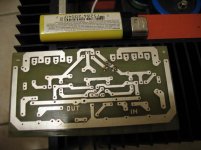
Finally I designed the layout for the PC board and I each the boards .
Unfortunately and sadly I just realised most of those transistors are no longer in production after 20 years . They are no longer in production .
I can find BDW93C/94C which is equivalent to the bigger brother BDW83C /84C but with less power .Still it would be enough with 40V rail voltage , and I plan to use 2pair of course .
Unfortunately the driver BF469 /BF470 hard to find parts , also with BC414C /416C have the same issue .
If anybody knows any info about these transistors please inform me .
Thank you . Now after I made the PC boards I really want to build the amp .
Any help greatly appreciated .
Thank you
Greets
Attachments
- Home
- Amplifiers
- Solid State
- My first DIY amplifier 20 years a go