The Vbe transistor can be any size. sot23 is nice and small and can be placed anywhere.
Glue the sot23 unside down to the collector leg that comes out of the hottest output device.
Short two legs of the sot23, C to B, with a fine copper strand from a piece of flex.
Attach a two wire lead from B and E and run to the PCB location.
This is about the fastest reacting Vbe you can build. It will work better than any location you can find for a To126 and better than any To92.
Here is the last layout, to me look like these ready to go.
The Vbe switched from PNP to NPN some other tweak.
I will test it soon, I hope these mods will reduce some of the thermal drifting what I experienced at last build.
For the correct size set up the printer 43% .
The Vbe switched from PNP to NPN some other tweak.
I will test it soon, I hope these mods will reduce some of the thermal drifting what I experienced at last build.
For the correct size set up the printer 43% .
Attachments

Member
Joined 2009
Paid Member
Bigun
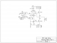
Here is the VBE U advised , from your TMG5
Those red are the new values plus the 47R extra resistor!
What do you think, can I test it how is it
If is OK just need the values to be adjusted I will mode the layout....
I will look for darlington transistor in the same package like the BD139, so I use faster device..
Greetings
I think there's supposed to be a diode in the Vbe multiplier circuit if you follow the TGM5 - will have to check (I am on travel at present).
I just left out that diode..
Now it if fixed, I hope no more error. That convert from PNP to NPN at Vbe gave a headache!
It took me a while until I got it right.
Thanks one more time pointing out that mistake")
By the way at the black and white layout next to all electrolyte caps a made a option to a small foil caps to.
Greetings
Now it if fixed, I hope no more error. That convert from PNP to NPN at Vbe gave a headache!
It took me a while until I got it right.
Thanks one more time pointing out that mistake
By the way at the black and white layout next to all electrolyte caps a made a option to a small foil caps to.
Greetings
Attachments
Bigun, ashok, Andrew & others who follow these thread.
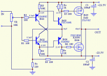
Can I test the Toshiba 2SK1530 & 2SJ201 mosfet if I add the green box parts and connection.
Is these correct
Please take a look at the modified schematic
Of is OK to test I will ad the mod to the layout to
Greetings
Can I test the Toshiba 2SK1530 & 2SJ201 mosfet if I add the green box parts and connection.
Is these correct
Please take a look at the modified schematic
Of is OK to test I will ad the mod to the layout to
Greetings
Attachments
a single 5.6v zener replaces all the bias network along with IRF530 & IRF9530 work perfectly here.
I have been using this since 1988 as a car amp.
mine has R7 = 2.2k , R5 = 560 T3 as a CCS and a LF353 as a dc servo
no 33p cap is required with current feedback design
Thank you
Can you post a scratch the way you use it.
You right about the 33p caps but that does not hurt or effect the sound, I do not have a scope to check for oscillation.
I used ISC darlingtons and at low level all blew up one after another after couple minutes, the same time half power ST BDW93C & 94C worked well.
I thought may be oscillation
All do I want to keep DC servo away fro these amp.
In case nothing work out to stabilize the thermal drift that will be the last option.
Some difference between the Toshiba mosfets and the IRF type
Greetings
Member
Joined 2009
Paid Member
Gaborbela, your latest schematic looks good (although my comments about capacitor sizes from earlier are not reflected in what you have shown - not critical but I remind you my thought is to use much larger on-board capacitors for the power rails next to the output devices). I'm not much of an expert on MOSFETs. They do make me nervous though - their tendency to oscillate at VHF just if you look at them! As a result, I have included gate-drain zobels on all my pcb layouts (for TGM7 and TGM8) - just small surface mount resistor and ceramic capacitors. You could put pads for them on the underside of the board just in case and use them only if needed.
Gaborbela, your latest schematic looks good (although my comments about capacitor sizes from earlier are not reflected in what you have shown - not critical but I remind you my thought is to use much larger on-board capacitors for the power rails next to the output devices). I'm not much of an expert on MOSFETs. They do make me nervous though - their tendency to oscillate at VHF just if you look at them! As a result, I have included gate-drain zobels on all my pcb layouts (for TGM7 and TGM8) - just small surface mount resistor and ceramic capacitors. You could put pads for them on the underside of the board just in case and use them only if needed.
I will start with a 100uF in that position, will increase it or decrease the value to see how to effect the sound.
AndrewT
here is a nice & simple CFB LatFet version
Probably too simple - in case someone interested
I do like the feedback connection
What do you think
Greetings
Attachments
Last edited:
Member
Joined 2009
Paid Member
I will start with a 100uF in that position, will increase it or decrease the value to see how to effect the sound.
That will be interesting. You may want to put footprint on the pcb for a larger cap according to how much space you can find, say up to 4,700uF ?
Bigun
To be honest I don't like to use large caps on the PC board.
Of course I will test larger value caps to in case that improve the whole amp performance .
If I rotate that capacitor I can go easily up to 1000uFor more depend on the capacitor size.
100 to 1000uF should be enough with the right power supply capacitor bank.
Do not forget these is a evaluation PC board.
If the thermal drift will be minimal or stable I can go back to correct, modify my old PC board around the Vbe - with that I can use two pair power transistor or Hitachi mosfet which perform better..
With higher rail Voltage these amp sound better, of course higher voltage need more power transistor.
I think about 50V rail voltage or so.
First think first
1) get read of the thermal drift, make the amp stable in a way to keep the performance.
2) test different Darlingtons and VAS.
3) test the Toshiba mosfets.
Greetings
I have not built any of these CFA style amps....................... AndrewT
here is a nice & simple CFB LatFet version
Probably too simple - in case someone interested
I do like the feedback connection
What do you think..............
I don't know what kind of feedback you are expecting.
What I can say is that the NFB is drawn to look like Global FeedBack. But it is actually feedback from 3rd stage to 2nd stage. It is a local feedback loop
Is there a reason that you drew is to mimic global feedback?
I note that your previous post showed vertical mosFETs and this one shows Lateral mosFETs.
My question was:
You appear to appreciate the difference, but the discussion seems to indicate some confusion in the different output bias requirements.are you two confusing the difference between Lateral mosFETS and Vertical mosFETs?
................. I don't like to use large caps on the PC board.
Of course I will test larger value caps to in case that improve the whole amp performance .
If I rotate that capacitor I can go easily up to 1000uFor more depend on the capacitor size.
100 to 1000uF should be enough ...............local decoupling should be sized to attenuate the voltage glitches that occur on the voltage supply lines inside the various locations of the amplifier.
Smoothing capacitance is in general about 10times larger and located at the other end of inductive supply leads.
"large value caps" is a relative term.
I have used upto 2200uF in parallel pairs (8800uF on PCB) on some amplifiers.
I have also used a PCB that had provision for two off 10mF on board AFTER the supply rail fuses. What a complete balls up !!!
I changed that to 3pairs of 1mF (6mF of local decoupling) in the space provided.
But it was located in the wrong place. It was all at one end of a long output stage.
- Home
- Amplifiers
- Solid State
- My first DIY amplifier 20 years a go