Hi G, I used the 40V supply because that's what I had working at the moment. I do have a lower V supply somewhere . Will have to search it out.
Will try to check out the LatFet version later today. Can be done with the same setup I have now.
But the sound is very good as it is. I'm using it without an input capacitor. Will try some boutique input caps later. As you said, the NFB dc blocking cap bugs me. Have to get something better.
The amp in the link I gave earlier is partly similar to yours. Input stage is different but the NFB stage doesn't require a dc blocking cap. In your's the dc blocking cap cannot be avoided. Of course the amp on that site has to use JFET's at the input to be able to avoid the input and NFB caps.
So many things to try out and there isn't enough time !
Bigun thanks for your help !
Yes I will accept all yours and Gaborbela suggestion to start with lower +/- 31 VDC from 300W C core transf. based PSU . heavy filtered with 44000uF per rail .
Since basically I don`t need many power for my very sensitive 16 ohm speakers .
BTW , what do you think about my idea to attach drivers & VAS transistors on big & earthed heatsink alltoghether with 3 temperature sensing diodes and 4 power transistors ? , since all components of this SS amp will be connected using short as possible wires and underside chassis PTP technique same as for some tube Amp ?
Best Regards !
Last edited:
If the amp.is 20yrs old,the electrolytics will probably have dried out and may well have a much reduced capacitance.Replace with good quality components,not "Brand-X"!
If you are considering replacing the output stage,Toshiba are making a range of Bipolars for audio amps.I have used the 2SC5200 and its complement 2SC19??.Beware of non-genuine devices,there is a warning out on the web that fake transistors are on the market.
Make sure the PSU is up to scratch.
If you like the sound,stay with it !
Hi Alan Frobisher !
Not sure for which SS Amp you are refer ! , but if you refer for that old Japanese PA Amp I can say only next ,
Yes I have done recap with fresh & brand name Eletrolytics , both big PSU ones and small ones from Amp PCB , varied bias to higher value , raised value of PSU capacitance , and so on and so forth ....,
but this PA Amp continue only to work great and very stable for PA purposes , but for serious Hi FI home use was really Unacceptable bad sounding .
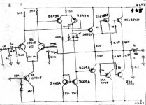
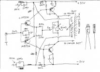
There is my scratch schematic taken directly from PCB of that Japanese PA Amp .
Finally I have disambled him for original Toshiba & Hitachi parts with main intention to DIY Amp based on very similar topology from Gaborbela Amp .
BTW , my opinion and experience is that SS Amps with differential input stage sounds bad ! , why is so explained scientist and Amp designer Mr.Bruce de Palma long time ago in his design white paper : Analog Audio Amplifier Design
Best Regards !
Not sure for which SS Amp you are refer ! , but if you refer for that old Japanese PA Amp I can say only next ,
Yes I have done recap with fresh & brand name Eletrolytics , both big PSU ones and small ones from Amp PCB , varied bias to higher value , raised value of PSU capacitance , and so on and so forth ....,
but this PA Amp continue only to work great and very stable for PA purposes , but for serious Hi FI home use was really Unacceptable bad sounding .
There is my scratch schematic taken directly from PCB of that Japanese PA Amp .
Finally I have disambled him for original Toshiba & Hitachi parts with main intention to DIY Amp based on very similar topology from Gaborbela Amp .
BTW , my opinion and experience is that SS Amps with differential input stage sounds bad ! , why is so explained scientist and Amp designer Mr.Bruce de Palma long time ago in his design white paper : Analog Audio Amplifier Design
Best Regards !
Attachments
Last edited:
Member
Joined 2009
Paid Member
BTW , what do you think about my idea to attach drivers & VAS transistors on big & earthed heatsink alltoghether with 3 temperature sensing diodes and 4 power transistors ? , since all components of this SS amp will be connected using short as possible wires and underside chassis PTP technique same as for some tube Amp ?
Best Regards !
If I understand you properly, you plan to have the bias spread diodes on the same heatsink as the output power devices. Of course this is a proper requirement. I prefer to use a single transistor instead of diodes for the bias as I find it easier to attach a single transistor than several diodes. If you look at my TGM5 thread (a symmetrical circuit like Gabor's) you will see my implementation of a single transistor (and one diode) bias spread / V(which varies with temperature unless it is heavily degenerated).
And you are thinking to have the input and VAS transistors on a separate heatsink ? I would suggest you do this as that might help to avoid them being heated up by the output power devices. The issue with the symmetrical VAS design like this is that the current through the VAS is poorly defined - any temperature changes in the VAS devices will result in the VAS current changing. Changes in the temperature of the input devices will also increase the VAS current. This in turn will change the voltage across the bias spreader (unless you use the Hagerman type of bias spreader) which changes the bias current through the output power devices. For optimal distortion in Class AB with bipolar transistors you want a stable bias.
I know Gabor has much experience with this amplifier and can advise on his experience with the thermal management considerations.
Last edited:
Member
Joined 2009
Paid Member
Amp designer Mr.Bruce de Palma long time ago in his design white paper : Analog Audio Amplifier Design
Best Regards !
I remember reading this a couple of years ago, although I was focussed on the tubes. Interesting (his circuit no. 3) option for improving temperature stability with the diode in the VAS emitter circuit. Not sure how it would affect the sound, but it looks like a viable option. However, in simulation it didn't do very well.
Attachments
Last edited:
Bigun
Yes my intention is to use original two separate big heatsinks from that old discarded Japanese Amp , each main big heatsink have carried 4 Toshiba power BJT , two PNP and two NPN , in middle between of that 4 power BJT`s was originally attached three bias spread diodes , brown ones, square shaped and stacked together , and with one central screw tighten to that main big heat sink , connected in bias circuit as is in my scratch schematic .
That original solution was keep the bias rock stable ! , same as DC offset which drift only few mV .
No excessive temperature was developed from that old Amp anyway , whatever how much hard was pushed .
Everything was just fine except sterile and artificial sound !
My idea is to drill new four small holes in each main heat sink , where two drivers BJT will be tighten beetwen each pair of power BJT , and two VAS BJT will be tighten left and right from bias spread diodes .
Input BJT pair will goes separately under the chassis ,with no heat sink but glued together !
Will check for TGM5 thread for sure !
Last edited:
Member
Joined 2009
Paid Member
Well it does depend on the topology of the old amplifier - it could be that it was less sensitive to temperature.
I had another read of the Hagerman paper which reminded that diodes are more stable than a simple Vbe multiplier with respect to VAS current changes: http://www.hagtech.com/pdf/vbe.pdf but if you read the paper you can do a lot better still.
If it were me, I would not put the VAS BJT's on the main heatsink - I wouldn't want the heatsink getting warm from use of the power output devices and then heating up the VAS. I guess you could isolate them from the main heatsink with some other material and use the main heatsink as a mechanical support only.
Last edited:
Bigun
Thanks for Hagerman paper !
From your suggestion I have learn something new and quit usefull !
Definitive I will place VAS transistors on the separate small and earthead heatsink under the chassis ! , taking care that to be close as possible to drivers transistors attached on main big heat sink , but not to close to input BJT pair .
Last edited:
I think this amp needs the bias transistor to be located as close as possible to the power transistors. I'm not quite sure if mounting it on the power transistor like it has been done in some commercial amps, will be better. The easiest way is to try it out. I'll do it with my module. Just wonder if there will be a space constraint as my power devices are below the board.
Of course with LatFET's the issue of bias drift doesn't really matter anymore.
I'm going to compare the two. If the LatFET sounds practically like the bipolar I'm going to drop bipolar output devices from this design .
Of course with LatFET's the issue of bias drift doesn't really matter anymore.
I'm going to compare the two. If the LatFET sounds practically like the bipolar I'm going to drop bipolar output devices from this design .
Hi
Yes it does look nice. I like these layout!
I thought you will go with 2 pair darlington. Of course if you go with 30-35V rail voltage (depend on the impedance of your speakers) even one pair will do the job.
Now I want to take a look the version which was modded by wahab.
According to him the 2PC 100K resister bad thik there..
Also he added some type of CCS, two zener diode (these mode was done long time but not tested yet) I do have the PC board for that test.
I'll test it soon.
I buy cheap 1% metal film resister these week for that test, I want to finish my high power Hitachi mosfet amp (just need some cheap parts and I can test that).
I bring these option to your att. just in case if you think it would be worth to ad to the PC board that extra two diode.
According to wahab these mode will help with the stability..
Mofet will not sound similar to bipolar.
The closest to bipolar the Exicon LatFet.
But that not mean you will not like how these amp would perform with LatFet.
If you build the amp after your new layout with those components I strongly believe you will be amazed with the performance.
Just use some better caps next time.
Greetings Gabor
Attachments
Member
Joined 2009
Paid Member
I would anticipate that differences in sound between the different output devices might be less noticeable when high levels of feedback are used. If I weren't wanting to reproduce a sound I heard 20 years ago then I'd go with the LatFETs and I'd save time by using Lazy Cat's pcb too. But as I have plenty of parts in my junk box (bipolars and darlingtons) I might prefer to use what I have, especially as I believe the sound will not suffer as a consequence.
I think having the bias spreader device on top of an output power device gives better thermal feedback (a hole in the pcb works - see my TGM5) - but you have to size the bias spreader resistors (operating point) to get the right level of sensitivity to temperature variation so that it doesn't over or under compensate.
I would suggest a provision on the pcb for a bypass capacitor for the VAS emitter resistors so that you can, if you choose, use larger valued resistors for better thermal stability and install a bypass cap to retain the gain at audio frequencies. I forgot to do this in my TGM5 pcb and so I am looking at how to add capacitors after-the-fact. I use large VAS emitter degeneration to get good thermal stability. This also means higher resistors in the collectors of the input pair - which raises gain and lowers distortion. It looks like a win-win combination on paper at least.
then I'd go with the LatFETs and I'd save time by using Lazy Cat's pcb too. But as I have plenty of parts in my junk box (bipolars and darlingtons) I might prefer to use what I have, especially as I believe the sound will not suffer as a consequence.I think having the bias spreader device on top of an output power device gives better thermal feedback (a hole in the pcb works - see my TGM5) - but you have to size the bias spreader resistors (operating point) to get the right level of sensitivity to temperature variation so that it doesn't over or under compensate.
I would suggest a provision on the pcb for a bypass capacitor for the VAS emitter resistors so that you can, if you choose, use larger valued resistors for better thermal stability and install a bypass cap to retain the gain at audio frequencies. I forgot to do this in my TGM5 pcb and so I am looking at how to add capacitors after-the-fact. I use large VAS emitter degeneration to get good thermal stability. This also means higher resistors in the collectors of the input pair - which raises gain and lowers distortion. It looks like a win-win combination on paper at least.
Last edited:
You can read when Lazy C chose the mosfet to the VAAS amp it was carefully chosen. I follow that thread to!
He compared LatFet to LatFet still got different result..
Last week or so someone just powered up the LC kit and compared with the same amp use Hitachi LatFet (was built while waited on the GB)..
According to him the LC kit sound much better right away!
I strongly (have a lot of experience specially with these amp) believe to a simple circuit like these parts must be carefully chosen and tested..
Swapping parts or changing their values can improve the sound a lot or decrease the sound very badly.. Like day and night.
One of the main reason I open these thread to get help to replace those old parts now no longer available. I heard these amp sounded terrible also heard the very the best sound among the amps I ever built!
I think only those understand clearly what I'm talking about who built these topology and did test research on it.
When I write these please do not feel I under estimate your knowledge.
I think here (at these topology) experience is a important factor like knowledge.
Please build the amp, swap some parts and you quickly will realise what I'm talking about.
Greetings G
Guys sorry if I jump in again ! , but ....
Just one quick question for Bigun related to thermal stability of this type of Amp :
Bigun check Gaborbela schematic from above ,
Question :what if we insert ordinary small NTC 50 Kohm / 25 C resistor in between of two hot end of C4 & C5 ? (220 uf ) , and that small trough hole NTC is tighten on main heat sink to sense output power devices temperature .
I think in that way we can control BJT input pair emitter`s DC current injection level in common mode , and to thermally stabilize whole Amp .
Maybe I`m wrong ....
Best Regards !
Last edited:
Member
Joined 2009
Paid Member
Hi Banat,
I did simulate such a scheme with my TGM5, although if I remember correctly it was not in the locations you mention but connected with the bias current for the input pair. In the schematic you reference it would be R3/4 and R29/30. It worked in my simulation and I did identify the parts from Digikey. I didn't try in the end because LC convinced me it wasn't needed and with the heavy degen of the VAS it did indeed turn out to be stable without any additional measures.
G - well if the LatFET is going to be really so much better I would give up my TGM5 and put it in the trash, then I would order some kits from LC......
Bigun
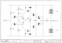
Here is my fast & ugly scratch schematic of my idea with NTC resistor as temperature compensation , it is same temperature compensation principle as I mentioned in one post before , related to Gaborbela schematic .
BTW ,
maybe I`m wrong but I think that NTC compensation between R 3/4 & R29/30 need two same NTC to be implemented , that solution of thermal compensation remind me on N.Pass F5 Amp .
This type of NTC ( 100K / 25C ) is common inside of PC SMPS PSU`s .
Attachments
Last edited:
Member
Joined 2009
Paid Member
I don't have the experience to know if there are some things to watch out for with Class AB (F5 is Class A) in terms of accuracy or how quickly the NTC responds to temperature changes but it looks like a valid approach. I think for F5 the idea is to wait until it has warmed up and then it just runs hot so it doesn't have to compensate accurately for temperature. You could do the same, but you could also make it more accurate with more effort - you may have to put fixed resistors in series or parallel (or both) with the NTC to tune it - an adjustable resistor might work best in practice which you could then replace with a permanent value once you have the amp set up in the chasis and have calibrated the right value by trial and error. Overall it looks simple and elegant and allows you to use devices other than LatFETs with more confidence.
Last edited:
Bigun
NTC react very fast to temperature change !
But you are right 100% ! , some experiment I have to made with this type of Temperature compensation to acomodate this simple solution in my real CFB Amp circuit, as you say maybe I need few NTC in series or in parallel , altogether with series or parallel trim pot ....
After all NTC`s are cheap and available .
G - well if the LatFET is going to be really so much better I would give up my TGM5 and put it in the trash, then I would order some kits from LC......
Bigun
What I wrote even between different LatFet can have such a sonic difference.
These info come from LC and another guy who built the VAAS with Hitachi and other mosfet.
It would be stupid from me to comment the BJT vs. LatFet since I didn't tested yet in these circuit.
Of course here is a huge factor the taste, what kind of sound we like.
Soft, warm, clinical, hard etc.
What I like at the darlington not clinical. has deep bass. clean sound but a bit warm not that soft like many mosfet type, neither the common BJT..
It has some special sound like NAIM but I think much better, cleaner, more dynamic with just a touch of warmness.
Actually I compared with the NCC200 which is better than NAP140 but still the same family and the darlington to me just other league.
Greetings G
- Home
- Amplifiers
- Solid State
- My first DIY amplifier 20 years a go