The heatsink will go on top of the output devices.
The heatsink is KS105 in this datasheet:
https://www1.elfa.se/data1/wwwroot/webroot/Z_DATA/07562077.pdf
Edit:
I will drill a hole in the heatsink for Q110.
The heatsink is KS105 in this datasheet:
https://www1.elfa.se/data1/wwwroot/webroot/Z_DATA/07562077.pdf
Edit:
I will drill a hole in the heatsink for Q110.
A 100mm length of the ks105 sink can dissipate 47W when DeltaT=70C, sitting in the vertical plane and with the fins oriented vertically. a 200m length can dissipate ~66W in the same conditions i.e. 200mm high.
Now look for DeltaT=20C, dissipation ~9W for 100mm high and ~12.5W for 200mm high.
This sink is far too small for your amplifier.
Why did I choose DeltaT=20C.
Let's look at a maximum ambient temperature of 28degC (Ta).
DeltaT=20C
heatsink temperature = Ta+ DeltaT =48degC
The thermal resistance from transistor case to heatsink (Rth c-s ~=0.5C/W) makes the transistor hotter than the sink.
If the design needs to dissipate 10W per device then Tc=Ts+DeltaTc-s ~=48+5=53degC.
Now de-rate your output devices for Tc=53degC. Oh, hang a moment, what if once device is passing a slighter higher current than it's partners? It requires to dissipate slightly more than average heat of it's brethern.
What if the part of the sink a device is attached to is not quite as efficient at dissipating heat as other parts? The device located here will run hotter than devices attached elsewhere.
To allow for these variations I like to add a Factor of Safety by allowing Tc to be 5Cdegrees hotter than average.
This factor of safety requires the hottest device to be de-rated for operation at 53+5 i.e. @ Tc=58degC
One can use a DeltaT>20C. If one adopts 30C then de-rate for Tc=68degC and so on.
If I limit the peak output voltage to 16V then the maximum power to the speaker (8 ohms) will be 16W for a sinusoid. That will (just guessing now) give me about 10 musical Watts, and that will be quite enough for me. Probably enough to make the neighbours call the police as well. Also the transformers will not be able to handle a whole lot more, I only got 60 VA.
I'm not sure about the efficiency of this thing but lets assume it's 50% then the maximum power dissipated in the sink will be no more than 16W.
That will make it run a bit hot but not go out in flames blazing inferno hot
The power planes(if i can fit any) will also draw some heat away into the pcb.
And if it gets to hot the uC can force the volume down or turn it off.
And as a last resort that I hope it will not come to I can mount a fan on top of the sink.
Hi,
if you plan to build a 16W amplifier then expect to get good quality music from it when the average output is approximately 0.16W (-20dB from maximum).
The 20dB overhead (about 10times voltage) allows short term transients to pass without being clipped. Some music requires the overhead to approach 30dB.
If you are using 88dB/W/m speakers at 2.5m listening distance then the average sound level at your seat will be approximately 75dB. That is about a loud conversation, but not shouting.
Why would that annoy the neighbours?
If you use CDs as a source then it seems to be about 10dB now, and decreasing all the timeAndrewT said:...The 20dB overhead (about 10times voltage) allows short term transients to pass without being clipped. Some music requires the overhead to approach 30dB...

Did you think I meant that systems should be designed around stupid marketing ploys?AndrewT said:Mr Evil,
do you intend to design your system specifically to suit badly recorded CDs?
I finally finished the pcb layout after taking som project time off.
The schematic and pcb layout
PCB Specs:
6 layers
280 x 225 x 2 mm (11.024" x 8.858" x 0.079")
35um copper on all layers
Electroless Nickle/Immersion Gold plating
The cards will cost 646 USD if I order 2 cards (exclusive shipping).
The schematic and pcb layout
PCB Specs:
6 layers
280 x 225 x 2 mm (11.024" x 8.858" x 0.079")
35um copper on all layers
Electroless Nickle/Immersion Gold plating
The cards will cost 646 USD if I order 2 cards (exclusive shipping).
Yes it's quite expensive.
If I order more cards it gets a bit cheaper:
5: 162 USD / card
10: 105 USD / card
15: 84 USD / card
20: 72 USD / card
Maybe someone else here is interested in building this thing to?
Hopefully there are no errors on the board but one can never be sure.
If I order more cards it gets a bit cheaper:
5: 162 USD / card
10: 105 USD / card
15: 84 USD / card
20: 72 USD / card
Maybe someone else here is interested in building this thing to?
Hopefully there are no errors on the board but one can never be sure.
I would like to ask why you did the following.
c2 and c3 instead of making c2 110uf and tieing it to ground.
the L bridge in q1 and q2
it looks like a push pull to me. If it is you might benefit from an opposing pair of silicon diodes q2 and where the output rejoins.
what is the purpose of R8?
other then that it all looks great to me.
c2 and c3 instead of making c2 110uf and tieing it to ground.
the L bridge in q1 and q2
it looks like a push pull to me. If it is you might benefit from an opposing pair of silicon diodes q2 and where the output rejoins.
what is the purpose of R8?
other then that it all looks great to me.
danfo098 , Your amp is nice , and should sound nice as well. BUT a DIY project should be both superior and more economical than it's OEM counterpart (it that exists).
I looked at your schema , and I must say you are spending WAY too much! Here is one SO close (mirror , CCS , even a faster VAS) .. all for 20 $ !!! (just the amp)
A single sided board resulted in -120db noise/hum and just took a couple of hours to draw/etch. For a first amp , make a couple of prototypes , run the hell out of them , fine tune degenerations/CDOM,biases (after simulation of course) , then when you get EXACTLY what you want , make the perfect layout along with high grade components. If you have a lot of loose change, spend it on the power supply / chassis ... to allow for future fanaticism..
OS
I looked at your schema , and I must say you are spending WAY too much! Here is one SO close (mirror , CCS , even a faster VAS) .. all for 20 $ !!! (just the amp)
A single sided board resulted in -120db noise/hum and just took a couple of hours to draw/etch. For a first amp , make a couple of prototypes , run the hell out of them , fine tune degenerations/CDOM,biases (after simulation of course)
, then when you get EXACTLY what you want , make the perfect layout along with high grade components. If you have a lot of loose change, spend it on the power supply / chassis ... to allow for future fanaticism.. OS
To bacon665:
I think you are looking at an older version of the amplifier but I'll try to answer your questions anyway.
Lower value capacitors generally have lower ESR (equivalent series resistance) meaning that it will be able to sink/source current faster than a capacitor with higher ESR. So having two (or more) capacitors of different values gives better decoupling over a wider frequency range.
q1 and q2 are current mirrors with the characteristic L bridge.
The purpose of R8 is to be able to adjust the quiscent current through the output stage. Lowering it will increase the bias voltage and in turn increase the quiscent current.
ostripper, I'm not into DIY to make bargains I just like to build stuff and if it gets a little pricy so be it. The satisfaction when you fire an amp up for the first time after building it yourself is almost priceless.
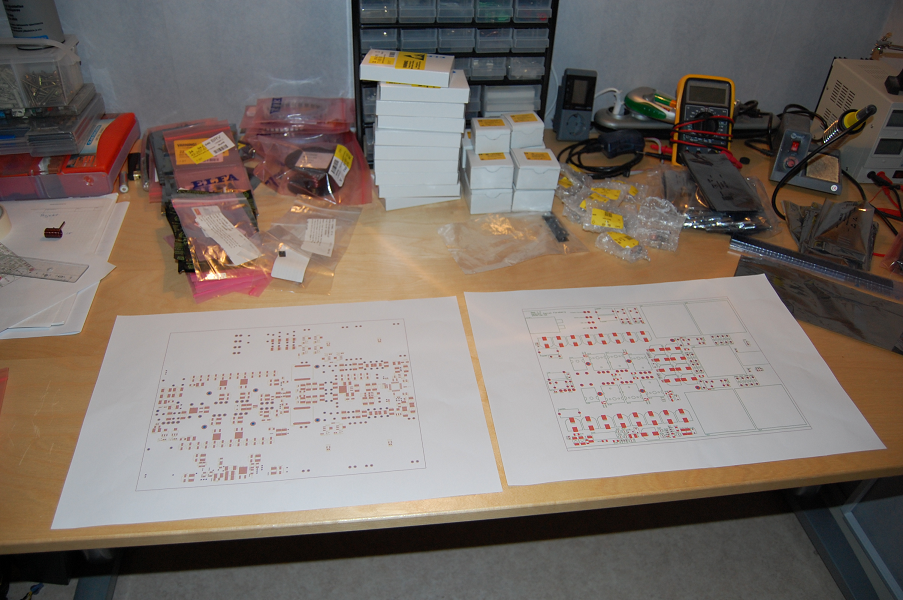
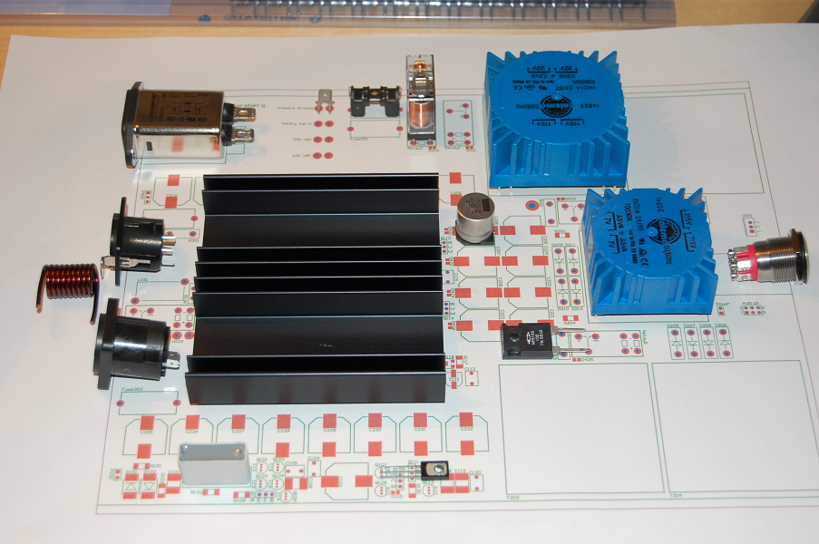
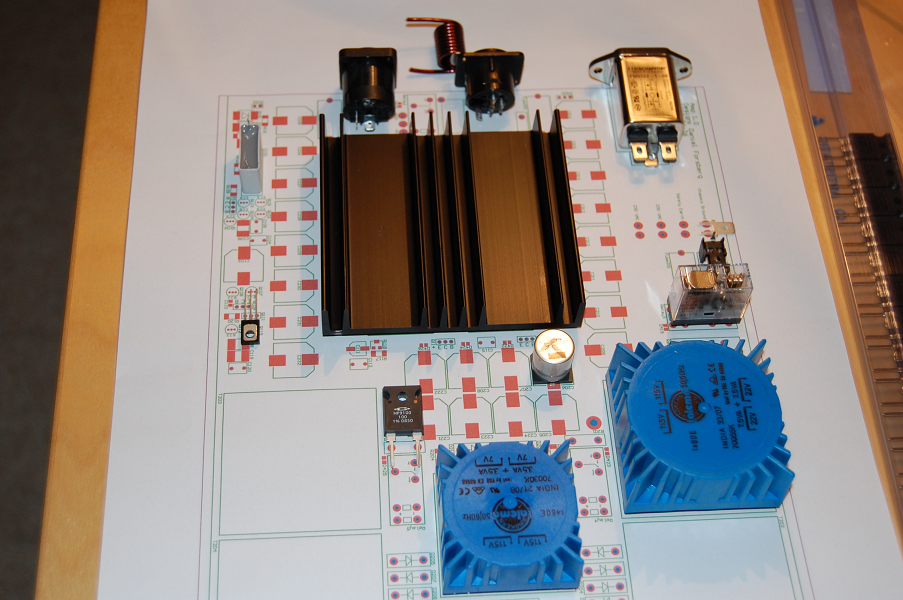
I'm going to order the components for the amps tomorrow. And when I get the components I'll match them to a printed 1:1 layout schematic to make sure all footprints are ok, then I'll order the pcbs.
Hopefully I will have one amp up and running before the end of my summer vacation.
Oh and for future fanaticism my next project will be a digital preamp for these amps with signalprocessing (equalizer etc) done in an FPGA, and there will be no el cheapo IIR-filters only massive FIR ones, I'm thinking like 100 taps per frequency band or so.
Remote control (433 MHz or bluetooth?) to the preamp with lcd(maybe graphical?) to display all 16 temp sensors in the amps, voltage, current and deliverd power in real time. The possibility to turn both amps off via the relays via the same remote. Also remote control of the filters in the equalizer and the vu-led on the power amps.
And lastly automatic/manual dynamic input voltage limiting depending on temperature and power in the amps.
Hopefully I will have one amp up and running before the end of my summer vacation.
Well looks like that's not going to happen. Only one week left
 .
.I haven't even ordered the cards because I spent a week in London this summer and it got a bit more pricy than I had anticipated so I think I'll wait until next months paycheck before ordering.
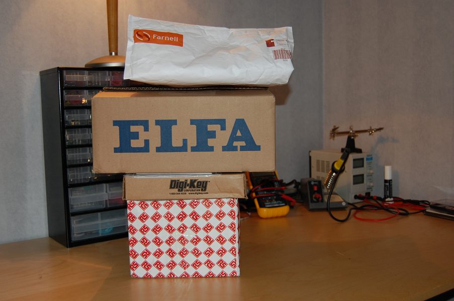
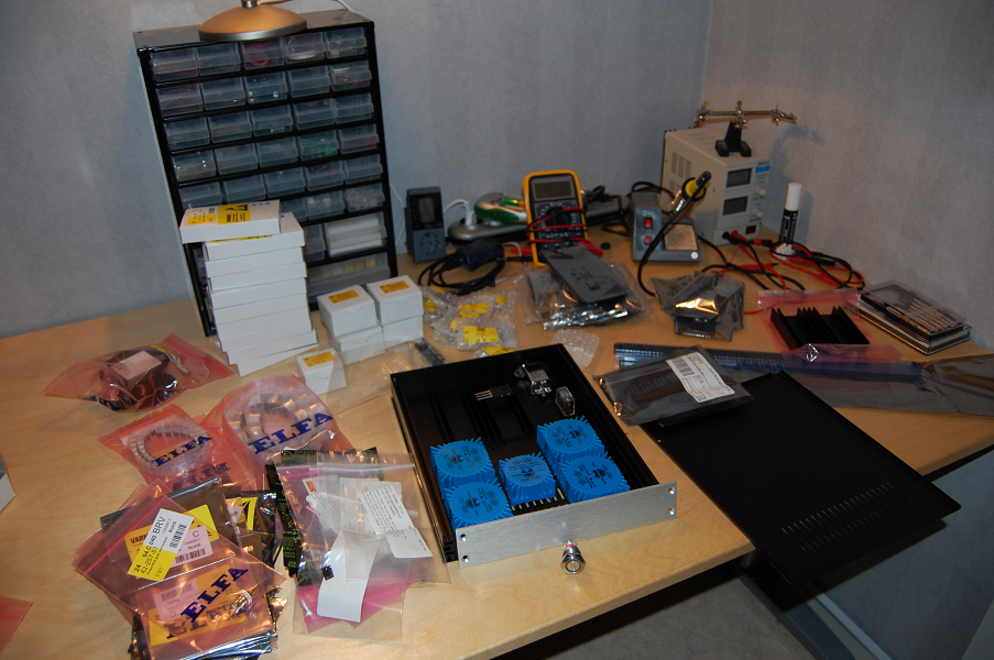
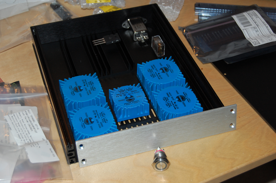
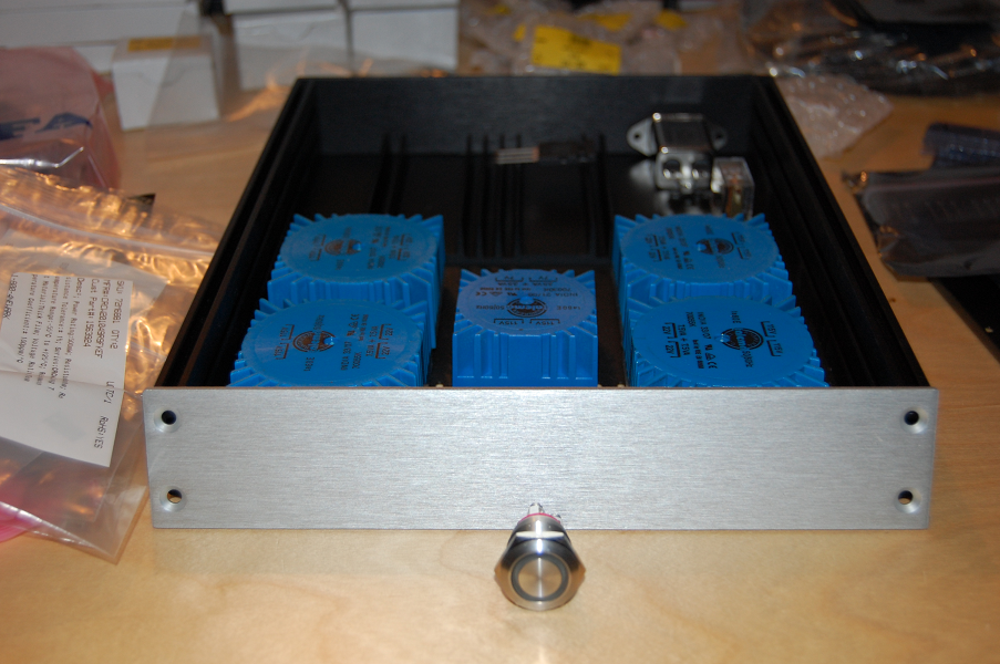
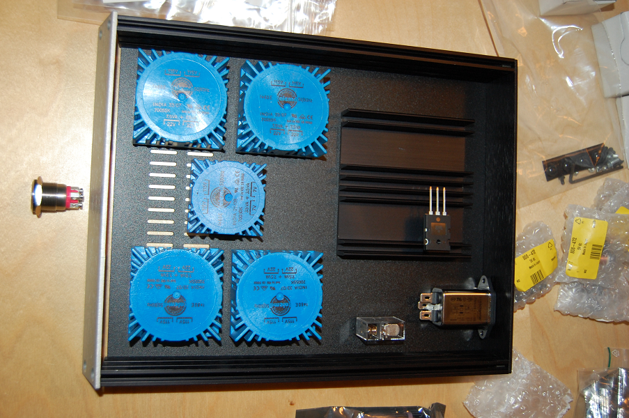
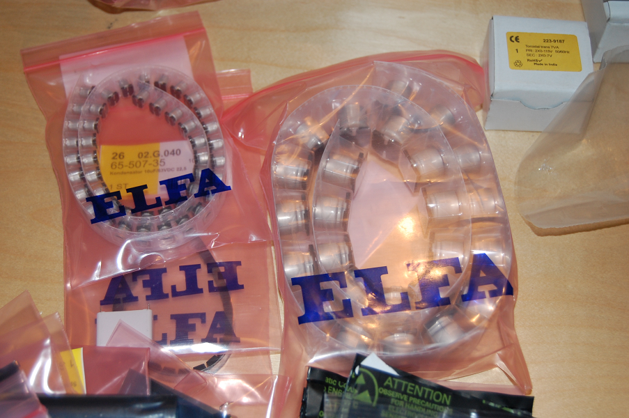
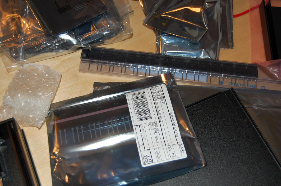
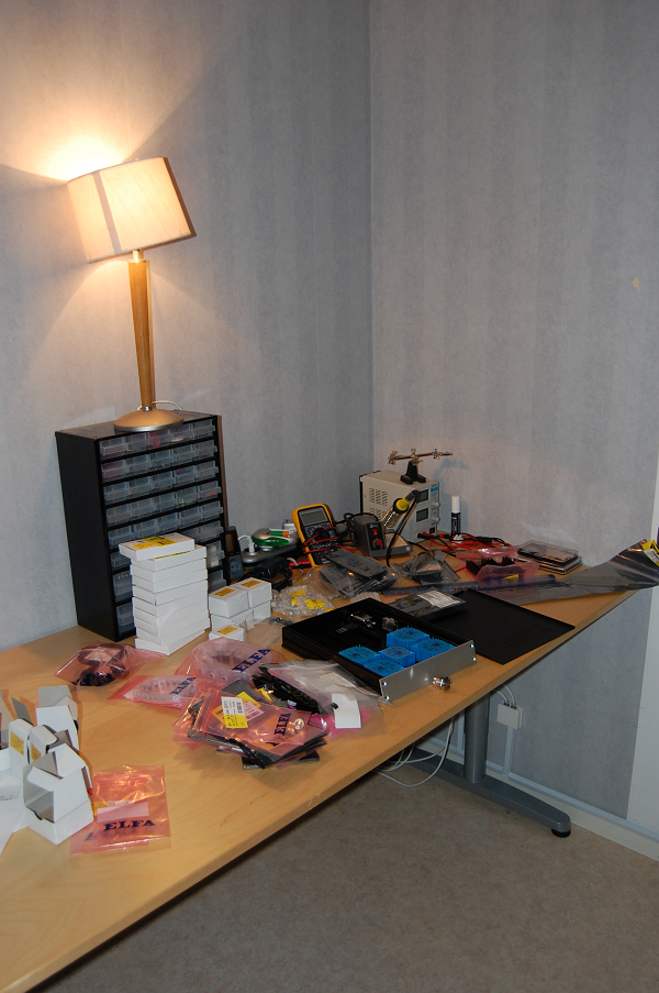
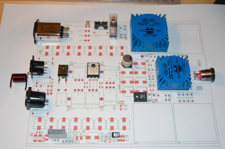
I got all the components though (except the uC) and here are some pictures in the mean time.
- Status
- This old topic is closed. If you want to reopen this topic, contact a moderator using the "Report Post" button.
- Home
- Amplifiers
- Solid State
- My first discrete amp