The B1 and DCB1 are not "weak" Buffers.It was written in an earlier post that the jfet is a weak buffer or similar.
They perform well when connected to reasonable load.
The Idss of the jFETs determines the maximum output current.
If you need more output current then you adopt a higher current capability Buffer.
Have a look at other Buffers with high output current. Calvin and F5 and BA-3 come to mind.
A Buffer does not have gain. The Maximum output is 1times the input (+0dB), but is usually a little bit less than that typically 0.95times (-0.4dB) to 0.99times (-0.1dB) the input signal.How do I set higher gain for that?
If you need gain then you don't use a Buffer, instead you use an amplifier and select the gain to suit your signal levels.
use the 5532. It is more likely to work well compared to the others.I am going to build an opamp input stage as well. I have a few to chose from(I'm not very familiar with what opamp is good for what):
AD797(soic8, don't remember letters after AD797), OPA627AU(bought several years ago on ebay, real or not I don't know), AD8066ARZ, OPA2111KP, OPA604AP, LT1360, LT1112, LT1077, OP282GSZ, NE5532 (philips and siemens marked), OPA2134, OPA2604. I have atleast two of the single opamps.
If you have the equipment and the skills, you can use some of the faster opamps, but these are MORE likely to misbehave if you don't get them exactly right.
AC or DC voltage?I get <5mV on one channel, >180mV on the other.
What were you measuring?
Last edited:
1/ A 'buffer' as we refer to it always has a voltage gain of 1 (or slightly under in practice). Buffers give current gain... and a FET buffer may well be far worse than the buffer in the source component feeding it, particularly when you think that a typical opamp can drive 600 ohms at full voltage swing.
2/
3/ You need to write down your requirements before you decide how and what to use. For example the range of input voltage it will see, the voltage gain you want and the input impedance you want. Also what the opamp is expected to drive, its impedance and whether it is a capacitive type load (such as along cable).
4/ Its always interesting to find the actual fault rather than just blanket change parts")
2/
3/ You need to write down your requirements before you decide how and what to use. For example the range of input voltage it will see, the voltage gain you want and the input impedance you want. Also what the opamp is expected to drive, its impedance and whether it is a capacitive type load (such as along cable).
4/ Its always interesting to find the actual fault rather than just blanket change parts
1. "weak" because it cannot deliver a lot of current. By nature it's an unity gain stage, you cannot change that without changing a lot of things.
2. opa2134 is a safe bet: it's unity gain stable, it is a jft opamp with high input impedance, it has very good specs all around.
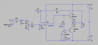
3. A good reason to avoid the ad797 at this stage... You could have a look at the "sapphire" amplifier by rjm. I'm not too fond of the design philosophy myself but it's a good start. If you want, I attach a simple schematic. It's simple but pretty decent: the output buffer works class a and so does the opamp.
2. opa2134 is a safe bet: it's unity gain stable, it is a jft opamp with high input impedance, it has very good specs all around.
3. A good reason to avoid the ad797 at this stage... You could have a look at the "sapphire" amplifier by rjm. I'm not too fond of the design philosophy myself but it's a good start. If you want, I attach a simple schematic. It's simple but pretty decent: the output buffer works class a and so does the opamp.
Attachments
The B1 and DCB1 are not "weak" Buffers.
They perform well when connected to reasonable load.
The Idss of the jFETs determines the maximum output current.
If you need more output current then you adopt a higher current capability Buffer.
Have a look at other Buffers with high output current. Calvin and F5 and BA-3 come to mind.A Buffer does not have gain. The Maximum output is 1times the input (+0dB), but is usually a little bit less than that typically 0.95times (-0.4dB) to 0.99times (-0.1dB) the input signal.
If you need gain then you don't use a Buffer, instead you use an amplifier and select the gain to suit your signal levels.use the 5532. It is more likely to work well compared to the others.
If you have the equipment and the skills, you can use some of the faster opamps, but these are MORE likely to misbehave if you don't get them exactly right.AC or DC voltage?
What were you measuring?
I'm sorry for leaving vital information out.
I meant DC offset. Measured outputs to gnd.
I have now, after some tinkering, gotten the DC offset down to a range of -8mV to +8mV (cold).
1/ A 'buffer' as we refer to it always has a voltage gain of 1 (or slightly under in practice). Buffers give current gain... and a FET buffer may well be far worse than the buffer in the source component feeding it, particularly when you think that a typical opamp can drive 600 ohms at full voltage swing.
2/
3/ You need to write down your requirements before you decide how and what to use. For example the range of input voltage it will see, the voltage gain you want and the input impedance you want. Also what the opamp is expected to drive, its impedance and whether it is a capacitive type load (such as along cable).
4/ Its always interesting to find the actual fault rather than just blanket change parts
3. I'm not sure of input voltage as the headamp will be feed from my modular DAC once it is ready.
I have a large number of different output stages for that DAC. The Pavouk.org unaltered schematic for DIR9001, WM8740. OPA2134(but with through hole top quality parts on perfboard).
I also have a nearly completed WM8805 board, a nearly completed PCM1794 board, another WM8740 on the way to try running two of them in mono, a Red Baron board and could I find 100% genuine PCM1704 at reasonable price, I'd build a module for that as well. I will end up using the combo that suits me best and have modules left over for atleast two more dacs lol
A number of different discrete output stages, and I plan to build the ECC86 + transistor "opamp" designed by Mr. Borberly.
I have the parts(except the 2SK216/2SJ79's that are on their way)
http://www.diyaudio.com/forums/solid-state/22883-borbely-low-voltage-hybrid-tube-mosfet-opamp-line-amp.html
I have an ECC86 output on my, modified, Analog Metric TDA1541A DAC in my main system.
That is a completely different circuit though, using 2SK170's as CCS, one half of the ECC86 per channel etc.
Anyway, the opamp would drive the Diamond buffer in this headamp project.
The Fidelio X2's are fairly easy to drive, but it's my experience that having "overkill" driving headphones, speakers etc effects SQ in a very positive way.
I am looking for the best possible SQ that I can manage out of this design.
I'm, if I say so myself, rather decent with the soldering iron. The areas where my DIY skills lack is design(recently got into that) and measuring as I don't (yet) own an oscilloscope.
Should the Jfet buffers I've built(I've build two of them now using matched quads of 2SK170's) not be suitable for this diamond buffer/design, I'll use them in some other project as there's no lack of projects out there using these jfets.
1. "weak" because it cannot deliver a lot of current. By nature it's an unity gain stage, you cannot change that without changing a lot of things.
2. opa2134 is a safe bet: it's unity gain stable, it is a jft opamp with high input impedance, it has very good specs all around.
3. A good reason to avoid the ad797 at this stage... You could have a look at the "sapphire" amplifier by rjm. I'm not too fond of the design philosophy myself but it's a good start. If you want, I attach a simple schematic. It's simple but pretty decent: the output buffer works class a and so does the opamp.
Thanks
I've looked at the Sapphire before, I even considered getting PCB's a while back.
I think you have to assume the output of a DAC will be around 2 volts rms at -3dBFS for a sine test signal. So that means you should design so that it handles at least 6 volts pk/pk input swing.
When it comes to sound quality things get a little more complex... for example an opamp such as an LM4562 will beat this kind of buffer hands down when it comes to driving a real load, however you might 'prefer' the sound of a JFET stage generating larger amounts of 2nd and 3rd harmonic distortion.
Its a no win situation. You use what sounds best to you.
I think you have to assume the output of a DAC will be around 2 volts rms at -3dBFS for a sine test signal. So that means you should design so that it handles at least 6 volts pk/pk input swing.
When it comes to sound quality things get a little more complex... for example an opamp such as an LM4562 will beat this kind of buffer hands down when it comes to driving a real load, however you might 'prefer' the sound of a JFET stage generating larger amounts of 2nd and 3rd harmonic distortion.
Its a no win situation. You use what sounds best to you.
After some thought, I've come to the conclusion that I'd probably prefer as neutral sound as possible...without loosing the "air guitarr" factor lol
My previous HP's were a bit on the bright side (Goldring DR150's).
Didn't have time to work on this headamp today. But I got the "JHL" Class A headamp as good as done.
Had it powered on for almost 90min and managed to trim DC offset (warm) down to from -15mV to +15mV, though most of the time it stayed below +/-10mVdc.
That is with 2pcs 2200uF lytics in series on the output.
Cold, this thing puts out over 200mVdc.
I'd never plug anything in to that headamp until after about 30min.
I'll try to find some schematic for "my" design headamp for an opamp-based input stage.
I've used the OPA2134 quite alot, and it's by no means bad but I'd like to try one of these opamps people are raving about.
I did use the LM4562 in the BCL clone for some time, it beat both NE5532 and OPA2134 IMHO.
Recently read that that is not a suitable opamp for that circuit however.
Is it really that hard to get something like AD797 stable in a circuit?
OPA2111KP is supposedly a nice opamp as well.
Got mine as samples some years ago along with some AD and LT opamps.
If you have caps in series with the output (your JLH) then the output should be at zero volts within seconds. Are you measuring the voltage with no load connected ? because that doesn't work due to the inherent leakage in the caps. Add say a 100 ohm to ground across the output and voltage should fall to zero very quickly.
That would simulate well Set up a cap across a 15 volt pulse and look at the exponential voltage decay across a load resistor on the other side.
I find the 4562 about as good as it gets when used correctly, however another terrific device that really does 'sound' a bit different but in a good way is the OPA2604 (single OPA604). I've used the OPA2134's in the past but never really enthused over them.
The AD797 is a device I've never used for audio but would suggest that if the design guidelines, and crucially the layout recommendations are followed then it should be fairly straightforward to work with. Layout is easier said than done though and just dropping it in as a replacement for other devices isn't going to work.
That would simulate well
Set up a cap across a 15 volt pulse and look at the exponential voltage decay across a load resistor on the other side. I find the 4562 about as good as it gets when used correctly, however another terrific device that really does 'sound' a bit different but in a good way is the OPA2604 (single OPA604). I've used the OPA2134's in the past but never really enthused over them.
The AD797 is a device I've never used for audio but would suggest that if the design guidelines, and crucially the layout recommendations are followed then it should be fairly straightforward to work with. Layout is easier said than done though and just dropping it in as a replacement for other devices isn't going to work.
If you have caps in series with the output (your JLH) then the output should be at zero volts within seconds. Are you measuring the voltage with no load connected ? because that doesn't work due to the inherent leakage in the caps. Add say a 100 ohm to ground across the output and voltage should fall to zero very quickly.
That would simulate well
I find the 4562 about as good as it gets when used correctly, however another terrific device that really does 'sound' a bit different but in a good way is the OPA2604 (single OPA604). I've used the OPA2134's in the past but never really enthused over them.
The AD797 is a device I've never used for audio but would suggest that if the design guidelines, and crucially the layout recommendations are followed then it should be fairly straightforward to work with. Layout is easier said than done though and just dropping it in as a replacement for other devices isn't going to work.
I've got both OPA2604 and 604's I got as samples year ago.
The AD797 and 827(?) are supposedly very good if used correctly.
I did run it un-loaded for trimming the DC-offset.
I've got a pair of resistors I use for setting my Vregs, 2x 220R 0.6W in paralell. That would make a decent load I suppose.
I wonder if trimming the offset as low as possible without load gave an ok output offset loaded or if I have to do it all over again.
Having lytic caps in the signal path is really not something I like. But I don't know if a servo can handle 300mV offset or more.
And apparently, I can't design a good DC-servo...mine don't seem to do the trick...
Btw, any way to have a permanent fix to drop the high offset to tolerable levels quickly? Like a bleeder in a PS, you get the idea.
I've ordered a HP protection circuit kit. It didn't say much in the listing, but from my understanding you can set those to switch on/off the relay by changing resistor/resistors or something like that.
Maybe I'm misunderstanding you here. If the amp is AC coupled to the load with a series coupling cap then can be no DC offset as seen by the load. It will always be 0.000 volts. How long it takes to get to 0.000 volts depends on the cap value and the load resistance.
The time constant (T) is T=C*R which would be a fraction under half a second for two 2200uf caps in parallel (so 4400uf) and two 220 ohms in parallel (110 ohm). To allow the voltage to reach 0.000 would require a period of around 5T.
The simulation shows an amplifier being switched on after 1 second and generating a voltage of 15 volts that must be blocked by the cap. After 2.5 seconds from switching on (so 3.5 seconds on the time scale) the voltage is pretty much zero.

A correctly designed servo can easily work with 300mv offset, although whether the amp should have 300 mv offset in the first place is another question... but yes, that's no problem for the servo.
The time constant (T) is T=C*R which would be a fraction under half a second for two 2200uf caps in parallel (so 4400uf) and two 220 ohms in parallel (110 ohm). To allow the voltage to reach 0.000 would require a period of around 5T.
The simulation shows an amplifier being switched on after 1 second and generating a voltage of 15 volts that must be blocked by the cap. After 2.5 seconds from switching on (so 3.5 seconds on the time scale) the voltage is pretty much zero.
A correctly designed servo can easily work with 300mv offset, although whether the amp should have 300 mv offset in the first place is another question... but yes, that's no problem for the servo.
Maybe I'm misunderstanding you here. If the amp is AC coupled to the load with a series coupling cap then can be no DC offset as seen by the load. It will always be 0.000 volts. How long it takes to get to 0.000 volts depends on the cap value and the load resistance.
The time constant (T) is T=C*R which would be a fraction under half a second for two 2200uf caps in parallel (so 4400uf) and two 220 ohms in parallel (110 ohm). To allow the voltage to reach 0.000 would require a period of around 5T.
The simulation shows an amplifier being switched on after 1 second and generating a voltage of 15 volts that must be blocked by the cap. After 2.5 seconds from switching on (so 3.5 seconds on the time scale) the voltage is pretty much zero.
View attachment 520949
A correctly designed servo can easily work with 300mv offset, although whether the amp should have 300 mv offset in the first place is another question... but yes, that's no problem for the servo.
I'm sorry, my bad. Not parallell, the lytics are in series + - - +.
I agree 300mV is too much.
From what I read in the JHL/JLH thread people having built this headamp get from 50mV to over 300mV DC offset.
Trimming offset to around 50mV or so may be ok for 600ohm HP's, but would likely fry my X2's.
If I try the DC-servo route again(I likely will), I'll take the DC "signal" straight from the pin of the output transistors.
I'll have to read up on where to best "inject" the outputs from the DC-servo.
Also to do is getting the hang of correctly designing a DC-servo.
Thanks.
So... a design such as this will never have any pretensions to DC precision without a servo. Variations in device parameters vs temperature mean that no matter how you try and set it up, its going to drift by a greater or lesser amount. That said, if you use a bipolar coupling cap (your 2200uf's back to back and in series) then there is no problem whatsoever.
Using it that way may be preferable to using a servo.
If you want to add a servo then you have two choices. You can use a simple single pole type consisting on an opamp integrator, which simply means the opamp has a 0.1uf cap from inverting input to the opamp output together with a 1meg resistor from the main amp output to the inverting opamp input. The non inverting input is grounded. The opamp output connects to the bottom of R19 and all the bias components of the led, the preset etc are removed. So the opamp now takes care of all the biasing and the DC voltage at the amp output will be zero volts.
Another option is to do essentially the same thing but still keep the bias voltage reference. Now you would split the 220k into two series 100k's and feed the opamp output via as high a value resistor as possible into the junction of the two 100k's using a value that will still allow the opamp to correct the error. In practice that means a bit of trial and error.
Thanks for your helpThanks.
So... a design such as this will never have any pretensions to DC precision without a servo. Variations in device parameters vs temperature mean that no matter how you try and set it up, its going to drift by a greater or lesser amount. That said, if you use a bipolar coupling cap (your 2200uf's back to back and in series) then there is no problem whatsoever.
Using it that way may be preferable to using a servo.
If you want to add a servo then you have two choices. You can use a simple single pole type consisting on an opamp integrator, which simply means the opamp has a 0.1uf cap from inverting input to the opamp output together with a 1meg resistor from the main amp output to the inverting opamp input. The non inverting input is grounded. The opamp output connects to the bottom of R19 and all the bias components of the led, the preset etc are removed. So the opamp now takes care of all the biasing and the DC voltage at the amp output will be zero volts.
Another option is to do essentially the same thing but still keep the bias voltage reference. Now you would split the 220k into two series 100k's and feed the opamp output via as high a value resistor as possible into the junction of the two 100k's using a value that will still allow the opamp to correct the error. In practice that means a bit of trial and error.
Marry Christmas!
I have read (I think I've mentioned that in an earlier post) that without DC-servo or large bipolar caps on the outputs, this circuit suffers from alot of DC offset caused by it's sensitivity to thermal changes (I have no clue if I'm making any sense here lol) and this thing runs HOT.
I have much larger heatsinks, but they won't fit unless I connect outputs on the bottom of the PCB or move the TIP41C's off board.
I almost completed a DC-servo I found in another thread here on DiyA (a desing by P-A Sjöström, a very good designer from my somewhat limited understanding).
That is meant to be tested with the BCL clone though.
Testing how fast DC offset drops with loaded outputs (110R 1.2W) now.
It is not as fast as has been suggested, that's for sure.
@ 3.5min it was down to around 5mVdc.
@ 4min it passed 0mVdc, then started climbing the negative scale.
Now howering around -40mVdc to -45mVdc for both channels.
I guess I'll need to trim the offset down again with the loads connected.
In the old days we had almost everything AC coupled.
That required a single polarity supply and coupling capacitors at the input and at the output.
Today we have dual polarity supplies and most amplifiers can be DC coupled at the output. Not many work well without the DC blocking capacitor at the input.
Your amplifier is a dual polarity supply with a DC coupled load and an AC coupled input.
If all the tempco exactly cancelled you would have no output offset and no change in offset as the amp warmed up from cold to full operating temperature.
But that ideal is nearly impossible.
You now have two choices. Add a DC servo to control the output offset, or add an AC coupling capacitor to the output.
The simplest by far is the AC coupled output.
But, there should be zero output offset if you build this correctly.
1. Did you reform the electrolytic capacitors?
2. Did you add the leakage correction resistor to the output?
3. Did you measure the output offset at the correct location?
Yes, merry Christmas 
-------------------------------------------------------------------------------
As you say, this design of amp suffers from DC drift and that is entirely normal and to be expected. You will never be able to trim the offset to zero and then get it to stay put. That's never going to happen on this type of circuit (assuming no servo).
Now then, you say the DC 'offset' isn't hitting zero for several minutes. Is that as measured at the output transistors or after your additional series coupling cap ?
If its at the transistors and the amp has no servo then its normal.
If its measured after the coupling cap then its not normal, and that applies whether the amp has a servo or not. This assumes the load resistor is also after the cap and not before.
Have a look at this servo. This shows the output of the amp as power is applied (rails appear at 1 second in) and then at 8 seconds the audio is applied to the input. I've attached the .asc file as well.
Attachments
In the old days we had almost everything AC coupled.
That required a single polarity supply and coupling capacitors at the input and at the output.
Today we have dual polarity supplies and most amplifiers can be DC coupled at the output. Not many work well without the DC blocking capacitor at the input.
Your amplifier is a dual polarity supply with a DC coupled load and an AC coupled input.
If all the tempco exactly cancelled you would have no output offset and no change in offset as the amp warmed up from cold to full operating temperature.
But that ideal is nearly impossible.
You now have two choices. Add a DC servo to control the output offset, or add an AC coupling capacitor to the output.
The simplest by far is the AC coupled output.
But, there should be zero output offset if you build this correctly.
1. Did you reform the electrolytic capacitors?
2. Did you add the leakage correction resistor to the output?
3. Did you measure the output offset at the correct location?
There are caps on the input, after the attentuator (C13) the kit came with a 470nF film cap, I added a 1uF parallell on the bottom of the PCB. But I may very well be misunderstanding you on this.
1. I have no clue what that means, I'll google it.
2. The load resistors? If so then yes.
3. I measured it as shown below
Other probe connected to gnd, cable used is 3.5mm stereo to RCA(with a 3.5mm to 6.3mm adaptor)
An externally hosted image should be here but it was not working when we last tested it.
- Status
- This old topic is closed. If you want to reopen this topic, contact a moderator using the "Report Post" button.
- Home
- Amplifiers
- Headphone Systems
- "My" first design headamp, DC-servo question